261 USFQ 8-bit Tracking ADC and Process Variation Monitor
261 : USFQ 8-bit Tracking ADC and Process Variation Monitor
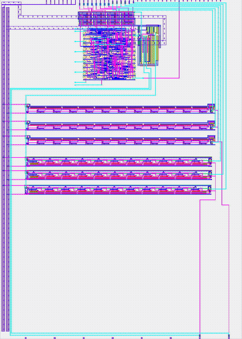
- Author: Esteban Astudillo, Raul Villalba, Diego Guevara, Emilia Casares
- Description: SKY130 mixed-signal chip integrating an 8-bit tracking ADC and an on chip process variation monitor.
- GitHub repository
- Open in 3D viewer
- Open in Tiny Tapeout Explorer
- Clock: 100000000 Hz
# USFQ 8-bit Tracking ADC and Process Variation Monitor
This project integrates two mixed-signal circuits implemented in the SKY130 process:
1. An 8-bit tracking analog-to-digital converter.
2. An on-chip process variation monitor based on NMOS and PMOS ring oscillators.
The design operates from the 1.8 V VDPWR supply.
## How it works
### 8-bit Tracking ADC
The tracking ADC compares the analog input voltage with the output of an internal DAC.
According to the comparator result, an 8-bit up/down counter is incremented or decremented.
The counter output drives the DAC and represents the digital conversion result.
The ADC input is connected to ua\[0], and the 8-bit conversion result is available on
uo\_out\[7:0].
### Process Variation Monitor
The process variation monitor contains NMOS and PMOS ring oscillators whose frequencies
depend on the fabricated process characteristics.
The oscillator outputs are conditioned and measured using frequency-to-digital converter
blocks. The resulting digital values are compared against predefined thresholds to classify
the NMOS and PMOS devices into slow, typical, or fast process regions.
The classification outputs are available through uio\_out\[5:0].
The ring oscillator signals are also available on uio\_out\[6] and uio\_out\[7] for direct
frequency measurement.
## How to test
### Tracking ADC
1. Power the design using the 1.8 V VDPWR supply.
2. Enable the project.
3. Apply a clock signal to clk.
4. Apply an analog voltage to ua\[0].
5. Read the ADC conversion result from uo\_out\[7:0].
6. Change the input voltage and verify that the 8-bit output tracks the applied voltage.
### Process Variation Monitor
1. Power the design using the 1.8 V VDPWR supply.
2. Enable the project.
3. Apply the reference clock to clk.
4. Release reset using rst\_n.
5. Observe the process classification outputs:
- uio\_out\[0]: NMOS slow
- uio\_out\[1]: NMOS typical
- uio\_out\[2]: NMOS fast
- uio\_out\[3]: PMOS slow
- uio\_out\[4]: PMOS typical
- uio\_out\[5]: PMOS fast
6. The ring oscillator frequencies can be measured directly using:
- uio\_out\[6]: NMOS ring oscillator monitor
- uio\_out\[7]: PMOS ring oscillator monitor
IO
| # | Input | Output | Bidirectional |
|---|---|---|---|
| 0 | COUNT[0] | ||
| 1 | COUNT[1] | ||
| 2 | PMOS_RING_3 | COUNT[2] | |
| 3 | PMOS_RING_2 | COUNT[3] | |
| 4 | PMOS_RING_1 | COUNT[4] | |
| 5 | NMOS_RING_3 | COUNT[5] | |
| 6 | NMOS_RING_2 | COUNT[6] | |
| 7 | CLK_IN | NMOS_RING_1 | COUNT[7] |
Analog pins
ua | PCB Pin | Internal index | Description |
|---|---|---|---|
| 0 | T | 9 | VDAC |
| 1 | U | 8 | VIN |