750 Configurable FIFO-buffered UART with APB CSR
750 : Configurable FIFO-buffered UART with APB CSR
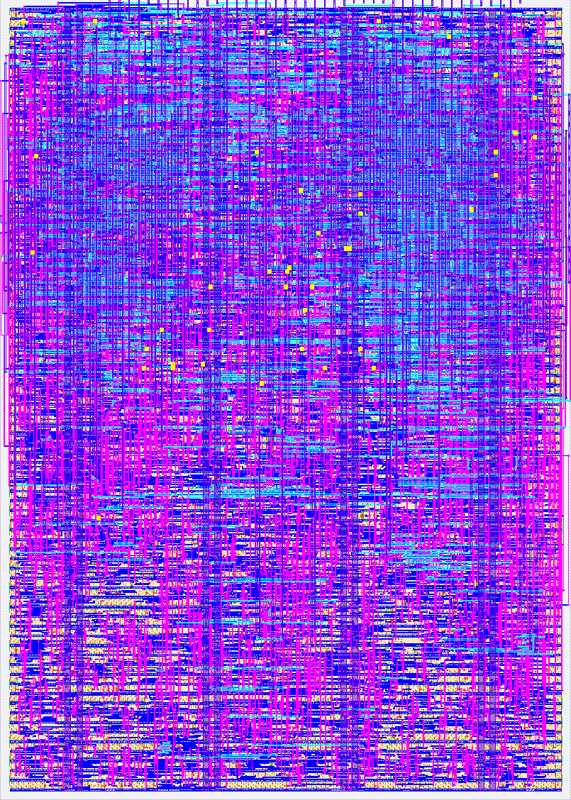
- Author: Drew Babel
- Description: A configurable, FIFO-buffered UART with an AMBA-APB register block, hardened to silicon on SkyWater SKY130 for the Tiny Tapeout shuttle.
- GitHub repository
- Open in 3D viewer
- Open in Tiny Tapeout Explorer
- Clock: 50000000 Hz
How it works
This is an 8-bit UART with 8N1 framing and optional parity, a 16-deep synchronous FIFO on each of the transmit and receive paths, and an AMBA-APB register block that makes the tile programmable at runtime over the pins it already has.
On transmit, the host presents a byte on ui_in[7:0] and pulses tx_push (uio[1]) to enqueue it into the TX FIFO. The strobe is two-flop synchronized and rising-edge detected, so a pulse of any width pushes exactly one byte. Hold ui_in stable from the rising edge until a few clocks after the pin is released. Hold both strobes low while reset releases, since a strobe already high at release counts as one edge. A small loader FSM hands buffered bytes to uart_tx one at a time whenever the transmitter is ready, shifting each out on tx_serial (uio[3]) as a start bit, 8 data bits (LSB first), an optional parity bit, and a stop bit. tx_full (uio[4]) signals the FIFO is full and the host should stop pushing.
On receive, the receiver oversamples rx_serial (uio[0]) at 16x, guards the asynchronous line with a two-flop synchronizer, and recovers each byte with mid-bit sampling that resynchronizes on every start edge, giving a clock-mismatch tolerance of about +/-4%. Recovered bytes land in the RX FIFO. rx_empty (uio[5]) is low when a byte is available, and the host pulses rx_pop (uio[2]) to read the oldest byte. The pop strobe is edge-detected like tx_push, and the byte appears on uo_out[7:0] a few clocks after the rising edge and stays until the next pop. rx_error (uio[6]) pulses on a framing or parity error, and the STATUS register latches error and RX-overflow events until a CTRL write clears them.
The register block is an APB slave the host reaches serially. Holding csr_mode (uio[7]) high, the host clocks a 12-bit frame of a read/write bit, a 3-bit address, and a data byte on csr_sclk and csr_mosi, MSB first. The csr_pin_adapter synchronizes the shift clock into the tile domain, assembles the frame, and issues one APB access into apb_csr. Keep csr_mode high for at least ten clocks after the last shift edge so the transaction lands. The registers turn on an internal loopback so the tile can exercise itself with no host, select even or odd parity, set a runtime baud divisor, and expose the FIFO status flags plus sticky error and overflow bits for readback. A read holds its byte on uo_out until csr_mode drops or the next frame starts.
How to test
The tile can verify itself with no external host. Shift a CSR write that sets loopback_en so uart_tx feeds uart_rx internally, push a byte through ui_in and tx_push, wait for rx_empty to go low, pulse rx_pop, and confirm the same byte reads back on uo_out. Shifting parity or baud-divisor writes first exercises those modes the same way.
For a real link, drive the design from a serial source at a baud rate matching the applied clock. The divisor is clock_hz / baud, so the default divisor of 434 gives 115200 baud at 50 MHz. The minimum valid divisor is 16, one clock per oversample point. For a different clock or baud, write the divisor to BAUD_LO and BAUD_HI. The receiver rounds it to the nearest multiple of 16, so keep the divisor within about 4% of a multiple of 16 (below roughly 250, use exact multiples). The default 434 rounds to 432, well inside tolerance. Connect tx_serial (uio[3]) and rx_serial (uio[0]) to a USB-to-serial adapter such as an FT232 and exchange bytes with a terminal, or tie the two lines together for an external loopback. Hold rx_serial high (its idle level) whenever no serial source is connected, since an undriven pin can read as noise and clock garbage into the RX FIFO.
External hardware
A USB-to-serial (UART) adapter such as an FT232RL breakout connects the chip's serial lines to a host terminal. None is required for the internal loopback self-test.
IO
| # | Input | Output | Bidirectional |
|---|---|---|---|
| 0 | tx_data[0] / csr_mosi | rx_data[0] / csr_rdata[0] | rx_serial (in) |
| 1 | tx_data[1] | rx_data[1] / csr_rdata[1] | tx_push / csr_sclk (in) |
| 2 | tx_data[2] | rx_data[2] / csr_rdata[2] | rx_pop (in) |
| 3 | tx_data[3] | rx_data[3] / csr_rdata[3] | tx_serial (out) |
| 4 | tx_data[4] | rx_data[4] / csr_rdata[4] | tx_full (out) |
| 5 | tx_data[5] | rx_data[5] / csr_rdata[5] | rx_empty (out) |
| 6 | tx_data[6] | rx_data[6] / csr_rdata[6] | rx_error (out) |
| 7 | tx_data[7] | rx_data[7] / csr_rdata[7] | csr_mode (in) |