Pinouts
To ease bring-up and make it easier to reuse boards, TT advocates to use common pinouts wherever possible. If your design uses the same pinout as some of the other designs, it is much easier to connect external hardware or create custom boards that are suitable for those designs.
The use of common pinouts is not mandatory, but is recommended since TT is a community shuttle. Feel free to deviate from the recommendations where it is necessary for your design. If you use a protocol or Pmod not listed here, please make a proposal on the Discord server.
Common Peripherals
UART to USB
If you want to interact with your design over serial console you can do this via the builtin RP2040 on the demo board. This way you can connect the demo board via USB and send/receive data from your chip.
You can use either:
ui_in[3] - RX
uo_out[4] - TX
or:
ui_in[1] - RX
uo_out[0] - TX
VGA Output
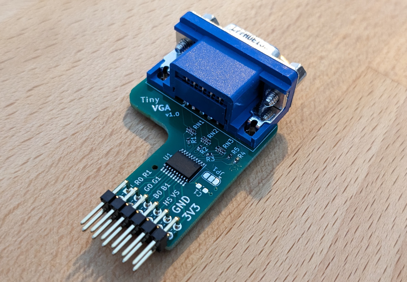
For VGA output, we recommended using the pinout of Tiny VGA. The board is open source and requires only one Pmod connector, so you can use the bidirectional Pmod connector of your Tiny Tapeout board for something else.
In case you plan to design your own carrier board, it still makes sense to use the pinout of Tiny VGA so that others can easily try out your design.
How to acquire a Tiny VGA?
You can either manufacture a Tiny VGA yourself or order one from the Tiny Tapeout Store.
Pinout:
uo_out[0] - R1
uo_out[1] - G1
uo_out[2] - B1
uo_out[3] - vsync
uo_out[4] - R0
uo_out[5] - G0
uo_out[6] - B0
uo_out[7] - hsync
Audio Output
For audio output, we recommend using the TT Audio Pmod. This open-source Pmod provides a simple way to output audio from your Tiny Tapeout design.
The pinout for the TT Audio Pmod is:
uio_out[7] or uo_out[7] - Audio Output
For stereo audio output, we recommend using pins 6 and 7 with the following convention:
uio_out[6] or uo_out[6] - Left Channel
uio_out[7] or uo_out[7] - Right Channel
This pinout allows for both mono and stereo audio output while maintaining compatibility with existing audio Pmods.
SPI RAM
The RP2040 on the demo board can be configured to provide RAM to the chip over SPI thanks to spi-ram-emu.
The pinout can be configured according to the project, but by default we suggest you use:
uio[0] - GPIO21 - CS
uio[1] - GPIO22 - MOSI
uio[2] - GPIO23 - MISO
uio[3] - GPIO24 - SCK
This maps to the standard SPI pinout for Pmods, which means a PSRAM Pmod could be used as a drop-in replacement.
Common Protocols (SPI, I2C and UART)
If you want to implement protocols that do not specifically target any Pmod we suggest to use the pinout for I2C, SPI and UART from the Pmod specification
SPI
SPI uses CS, MOSI, MISO and SCK and therefore requires only one row of pins of the Pmod connector, preferably the upper row. Since standard SPI has to send and receive, the bidirectional Pmod is used:
Top row:
uio[0] - CS
uio[1] - MOSI
uio[2] - MISO
uio[3] - SCK
Bottom row:
uio[4] - CS
uio[5] - MOSI
uio[6] - MISO
uio[7] - SCK
If your design only receives data or only sends data via SPI, you can choose to omit MOSI or MISO and use the output only or input only Pmod. SPI - dual I/O and quad I/O
See: https://digilent.com/reference/pmod/pmodsf3/start
uio[0] - CS
uio[1] - MOSI
uio[2] - MISO
uio[3] - SCK
uio[4] - NC
uio[5] - RST
uio[6] - WP
uio[7] - HLD
UART (optional hardware flow control)
UART uses TXD and RXD and optionally CTS and RTS. Only one row of the Pmod connector is used, preferably the upper row:
Top row:
uio[0] - (CTS)
uio[1] - TXD
uio[2] - RXD
uio[3] - (RTS)
Bottom row:
uio[4] - (CTS)
uio[5] - TXD
uio[6] - RXD
uio[7] - (RTS)
If your design is receive only or send only, you can choose to omit TXD or RXD and choose to use the output only or input only Pmod.
I2C (optional interrupt and reset)
The pinout for I2C uses SCL and SDA and optionally INT and RESET for interrupts and reset. Only one row of the Pmod connector is used, preferably the upper row:
Top row:
uio[0] - (INT)
uio[1] - (RESET)
uio[2] - SCL
uio[3] - SDA
Bottom row:
uio[4] - (INT)
uio[5] - (RESET)
uio[6] - SCL
uio[7] - SDA
QSPI Flash and PSRAM
This Pmod can provide access to external flash and RAM over SPI or QSPI. The pinout is:
uio[0] CS0 (Flash)
uio[1] SD0/MOSI
uio[2] SD1/MISO
uio[3] SCK
uio[4] SD2
uio[5] SD3
uio[6] CS1 (RAM A)
uio[7] CS2 (RAM B)
Game Controllers
The Gamepad Pmod takes the simple controller protocol and makes it unidirectional, so you don’t have to sacrifice bidirectional pins to leverage input from one or two SNES, Super Famicom or other compatible controllers. Let the games begin!
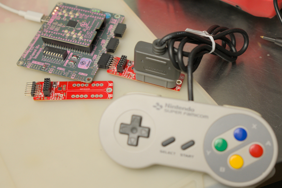
It only uses 3 of the input pins, so it’s possible to share the pins with other Pmods using the female host port.
The pinout is
ui_in[4] LATCH
ui_in[5] CLOCK
ui_in[6] DATA
To get started, check out the gamepad_pmod_single and gamepad_pmod_dual modules from the VGA Playground Gamepad example code. You can copy this file into your own project and connect it to the gamepad Pmod like this:
  gamepad_pmod_single gamepad (
      // Inputs:
      .rst_n(rst_n),
      .clk(clk),
      .pmod_data(ui_in[6]),
      .pmod_clk(ui_in[5]),
      .pmod_latch(ui_in[4]),

      // Outputs:
      .is_present(gamepad_is_present),
      .b(gamepad_b),
      .y(gamepad_y),
      .select(gamepad_select),
      .start(gamepad_start),
      .up(gamepad_up),
      .down(gamepad_down),
      .left(gamepad_left),
      .right(gamepad_right),
      .a(gamepad_a),
      .x(gamepad_x),
      .l(gamepad_l),
      .r(gamepad_r)
  );
If you are experiencing compatibility issues, you may need to update the firmware of your gamepad PMOD. See our guide on flashing your gamepad PMOD for more info.