Logic Puzzle - Padlock
In this puzzle, you’re a spy trying to gain access to a safe containing precious semiconductor equipment. Can you crack the code to gain access to the safe?
If the first puzzle is too easy, try the second more challenging one! You can also customize your own padlock!
Background
The circuit used for this puzzle uses both combinational logic and sequential logic.
This puzzle uses D-flip flops to create a sequential logic circuit called a finite state machine (FSM). Combinational logic is then used to determine under what inputs the circuit switches states.
For example, using FSMs we could design a basic circuit that becomes active while an input is 1 and remains active until the input goes to 0. To describe this with state machies, we could say that if the circuit is in State 0 (S0) and the input is 1, then it will proceed to State 1 (S1). While the input is 1, the circuit remains in S1. Once the input goes to 0, the circuit then returns to S0.
FSMs can be explained pictorally using state diagrams like this:
The state diagram depicts all possible states the system can be in while describing how the system transisitions between states.
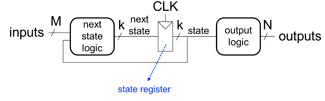
Digital logic can then be used to implement the FSM using three main components: next state logic, a state register, and output logic as depicted below (credit: Prof. Onur Mutlu’s 2019 slides, starting on page 49).
Puzzle 1: Easy Version
A safe containing precious semiconductor equipment has been locked using logic gates. You must enter the correct sequential code to unlock the system and capture the materials!
This puzzle implements the state machine below:
Note: “!” is commonly used to represent negation, a.k.a. “not”. So !Reset means Reset = 0
Controls
- The push button is used to enter your code.
- Switch 2 is used to reset the safe.
- Switches 3 to 5 are used to set code.
To begin
Press the green button in the top left of the simulation pane, then click to turn on Switch 2, and press the push button. The red LED labeled “Locked” should turn on and the seven segment display should show “L” (for locked).
Next turn off Switch 2 and begin testing codes. Set a code using Switches 3 to 5.
If you enter a correct code, you will see the cyan LED labeled “Unlocked!” turn on. Congratulations! The seven segment display should also show “U” (for unlocked).
| SW3 | SW4 | SW5 |
|---|---|---|
| 0 | 1 | 1 |
Puzzle 2: Harder Version
Uh oh, after your first break-in, the guards have increased security. Now you must enter three correct codes consecutively to gain access to the safe!
This puzzle implements the state machine below:
Controls
- The push button is used to enter your code.
- Switch 2 is used to enable the padlock. To reset at any time, toggle Switch 2 to 0 and back to 1.
- Switches 3 to 5 are used to set the code.
To begin
Set all switches to 0 and press the push button. A “-” will appear on the seven segment display.
When you’re ready, turn on Switch 2 and press the push button to begin the challenge. The yellow LED will turn on, and the seven segment display will show “L” for “locked”.
Next set a code using Switches 3 to 5. If you enter a correct code, you will see the colored LED progress from yellow –> magenta.
If you succeeded, try to get to the next stages, lighting the white LED then finally the cyan! A “U” will appear for “unlocked”.
If you fail to enter the correct code at any stage, you will return to the yellow LED.
Feel free to play around to try to figure it out. You can always return to the logic gate and flip flop tutorials if you need a refresher.
| LED | SW3 | SW4 | SW5 |
|---|---|---|---|
| Yellow | 1 | 0 | 0 |
| Magenta | 0 | 1 | 0 |
| White | 0 | 0 | 1 |