870 SeeTheBeat
870 : SeeTheBeat
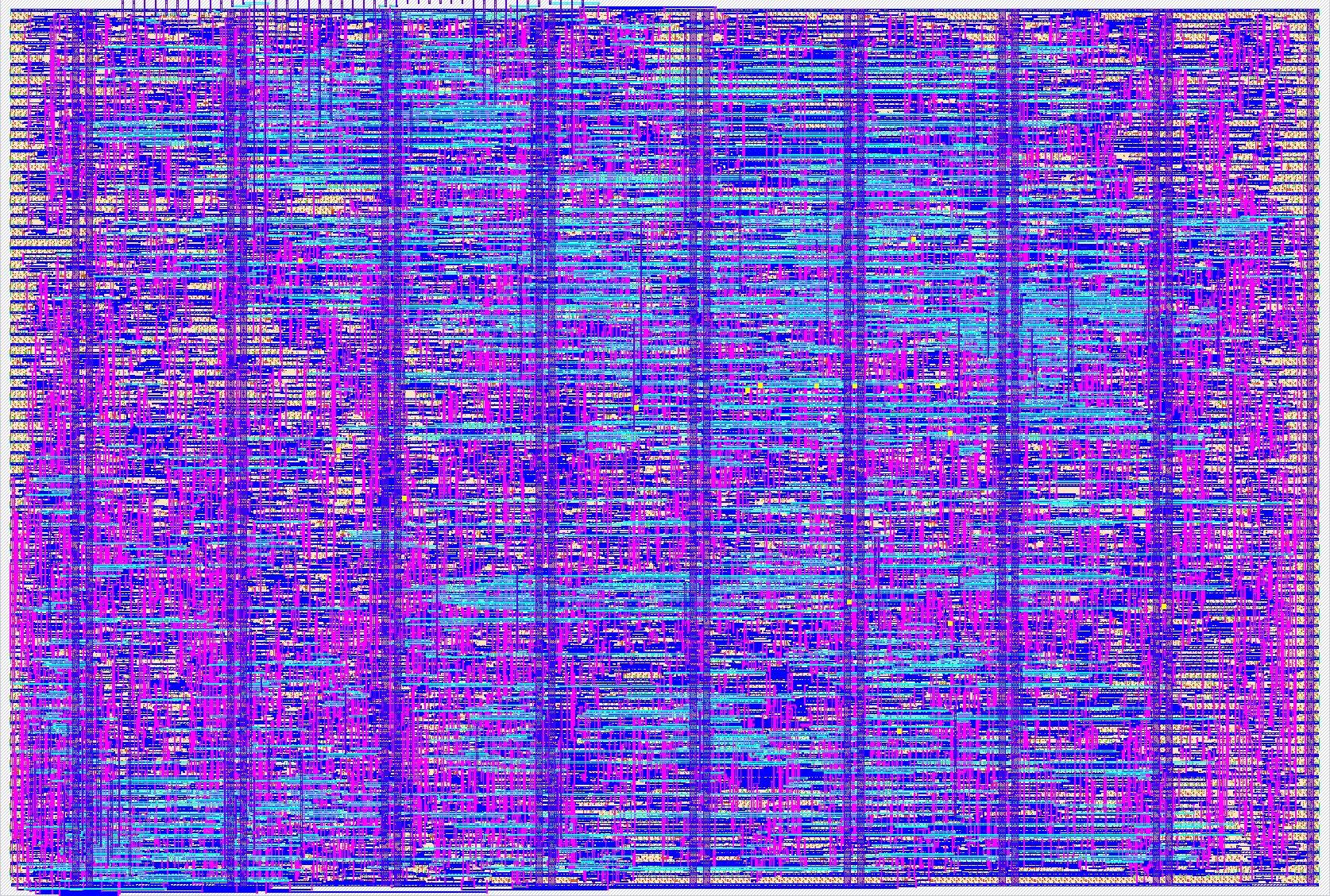
- Author: Jonas Creyns, Giel Swenters
- Description: Real-time audio visualizer: on-chip 512-point FFT driving a VGA display
- GitHub repository
- Open in 3D viewer
- Open in Tiny Tapeout Explorer
- Open in VGA Playground
- Clock: 40000000 Hz
How it works
SeeTheBeat is a real-time audio visualizer. The chip does the digital signal-processing and video generation; the Tiny Tapeout demo board's microcontroller (RP2040/RP2350) acts as the memory and audio front-end.
- Samples in. The microcontroller captures 16-bit audio samples into its SRAM.
- 512-point FFT (on chip). The chip streams samples over its bus and computes a 512-point Fast Fourier Transform to obtain the frequency spectrum. Because a 512-point working buffer (~2 KB) is far larger than on-chip memory allows, the buffer lives in the microcontroller's SRAM and the chip ping-pongs data with it on each of the 9 FFT stages. The butterfly uses a CORDIC rotator (no multiplier, no twiddle ROM); the transform is a scaled fixed-point (Q1.15) radix-2 design.
- Spectrum to visual state (on the microcontroller). The transform is left in place in the microcontroller's SRAM, so the microcontroller takes it from there: bin magnitude, log scaling, band summing, beat detection and the frequency-to-band map all run in firmware, where they cost no silicon area. It publishes a 20-word visual state: 16 band energies (5 bits each), a global kick-flash level, and three configuration words.
- Pixels + VGA out (on chip). Once per frame, during vertical blanking, the chip reads that visual-state block back over its bus and generates pixels procedurally as f(x, y, time, visual state) -- no frame buffer, no stored objects. Pixels are streamed over a Tiny VGA Pmod at 800x600 @ 60 Hz (40 MHz pixel clock), 6-bit color (RRGGBB) plus HSync/VSync.
The split follows from area: at 2x2 tiles the chip has room for the arithmetic that must run at pixel rate, and nothing else. Anything that can be decided once per frame is decided in firmware.
What you see
The screen is divided into 16 zones, each a level meter that fills from its own edge in proportion to its band, with brightness set by the band's top bits. A silent band is black -- the default picture is mostly black, which is the intent.
 px: 0       120                          680       800
     +-------+-----------------------------+---------+ py=0
     |  L4   | C12 | C13 | C14 | C15        |   R8    |  highs hang DOWN
     +-------+   4 centre columns,          +---------+  from the top
     |  L5   |   140 wide, 360 deep         |   R9    |
     +-------+                              +---------+
     |  L6   |                              |   R10   |
     +-------+                              +---------+
     |  L7   |                              |   R11   |
     +-------+-----------------------------+---------+ py=360
     |  B0   |   B1    |   B2   |   B3               |
     |        bass, 240 deep, fills UPWARD           |
     +-----------------------------------------------+ py=600
      side wings 120 deep, fill inward, rows of 90
Three effects run on chip, all functions of position and time so they need no storage: a breathing zone edge (a triangle wave on the frame counter nudges each bar's tip), a kick flash (a global white lift, saturating so it can never wrap to black on the beat), and a soft fade on each bar's tip resolved by a 4x4 ordered dither, which gets roughly 16 apparent brightness levels out of the 4 the Pmod can express.
Everything about the look is firmware-controlled through three config words: greyscale, one of four palettes, a global brightness dim, the breathing amplitude, and the fade's width. All of them are defined so that all-zero means the default look, so firmware that publishes only band values still gets a correct picture.
How to test
With nothing but a clock and a monitor. The chip's visual state powers up to a ramp
(1, 3, 5 ... 31 across the 16 bands), so with only clk, rst_n and a Tiny VGA Pmod --
no microcontroller, no audio -- it draws every zone at a different height, in colour,
and animates. That single picture checks the VGA timing, both sync polarities, the Pmod
bit order, the zone geometry and the blanking gate at once. Start here.
With the microcontroller. Firmware loads 512 audio samples into SRAM and then acts as
a memory slave, answering the chip's read/write requests while the FFT runs, and serving
the visual-state block from a separate config address space when the chip asks for it
during vertical blanking. The wire protocol is documented in docs/bus_protocol.md.
Verification. Every RTL block has a cocotb testbench comparing it bit-for-bit
against a pure-Python golden model in model/: the CORDIC, the butterfly, the full FFT
(against a reference transform), the bus, the VGA timing, the register file and the pixel
generator. The pixel path is checked over complete 663,168-clock frames for every
configuration value, including that nothing is ever lit during blanking.
External hardware
- Tiny VGA Pmod (on the dedicated outputs) driving a VGA monitor.
- The demo-board microcontroller (RP2040 or RP2350) as the sample memory and audio ADC front-end, connected over the input and bidirectional buses. Optional for a first look -- see "How to test" above.
- Optionally, potentiometers on spare microcontroller ADC inputs: because every visual parameter is a value the microcontroller publishes, physical knobs for brightness, palette, breathing and fade cost no silicon at all.
IO
| # | Input | Output | Bidirectional |
|---|---|---|---|
| 0 | din0 | R1 | cmd0 |
| 1 | din1 | G1 | cmd1 |
| 2 | din2 | B1 | cmd2 |
| 3 | din3 | vsync | cmd3 |
| 4 | din4 | R0 | cmd4 |
| 5 | din5 | G0 | cmd5 |
| 6 | din6 | B0 | frame_ready |
| 7 | din7 | hsync | resp_valid |