878 Interactive Conway's Game of Life
878 : Interactive Conway's Game of Life
- Author: Mathias Van Nuland, Sander Vanlessen, Sieben De Witte
- Description: Interactive VGA Conway's Game of Life on Tiny Tapeout with toggleable bounded/toroidal modes and cursor-based cell editing.
- GitHub repository
- Open in 3D viewer
- Open in Tiny Tapeout Explorer
- Open in VGA Playground
- Clock: 25175000 Hz
Note: links are embedded in the pdf and are in italic.
Description
This project simulates Conway's Game of Life. Conway's Game of Life is a classic cellular automaton simulation where cells on a grid live, die, or reproduce based on a small set of rules applied to their neighbors. Originally devised by mathematician John Conway, it demonstrates how complex, evolving patterns can emerge from simple deterministic logic - no player input required once the initial state is set. Perfect for programming into a chip.
Features
- 16x12 grid, 40 pixel cell size
- User editable grid with movable cursor
- User changeable simulation speed (0.25–20 Hz)
- Two modes: 'torus' and 'bounded'
- Pause/play button
- Debounced input handling
- VGA screen 640x480@60Hz
How it works
Input
There are four button inputs for moving the cursor up, down, left, and right. These buttons increment or decrement two counters in the row and column directions to determine the correct write address. A set button is used to toggle between a cell that is alive or dead. The start/stop button allows the simulation to be started or paused, while the cursor on/off button can be used to show or hide the cursor. The user can only edit the grid when the cursor is on. There are also buttons to increase or decrease the speed of the simulation, and a reset button. The final button toggles bounded board mode, which determines whether the simulation wraps around at the grid edges. All buttons are debounced and synchronized, this means that short mechanical bounce is filtered out and each button level is brought onto the system clock before it is used. The design therefore sees clean, stable inputs that all modules sample at the same time.
| Pin | Button | Behaviour |
|---|---|---|
| ui_in[0] | up | move cursor up |
| ui_in[1] | down | move cursor down |
| ui_in[2] | left | move cursor left |
| ui_in[3] | right | move cursor right |
| ui_in[4] | set | toggle the selected cell between alive and dead |
| ui_in[5] | start/stop | start or pause the simulation |
| ui_in[6] | cursor | turn the cursor on/off |
| ui_in[7] | board | toggle between bounded and torus modes |
| uio_in[0] | speed up | increase simulation speed |
| uio_in[1] | speed down | decrease simulation speed |
| uio_in[2] | reset | reset the grid |
| uio_in[7] | testing | only for virtual simulation -> update grid every frame and disable debouncing |
Memory
The register_board module stores the grid state using two complementary memories. board0 is a random access grid used by input, VGA, and logic to read and write cell states (0 = dead, 1 = alive). board1 is a shift register buffer that stores the previous grid iteration for logic computations; it uses a shift register instead of random access to reduce area overhead.
Both boards share data_in, write_enable, and data_out ports, with active_board_read and active_board_write multiplexing access. board0 uses indexed addressing (read_address_row, read_address_col, write_address_row, write_address_col) for random access, while board1 is controlled by toggle_read to shift through cells sequentially. When reading from board1, the module outputs the current cell via data_out and its eight neighbors via neighbour_out. manual_reset clears both boards to all zeros.
Logic
The logic module updates the grid during each VGA vertical sync (vsync) period, but only if the next_iter_countdown module indicates enough time has elapsed since the previous update. The countdown threshold is determined by the simulation speed setting (0.25Hz to 20Hz); a faster speed requires fewer clock cycles to elapse, while a slower speed requires more.
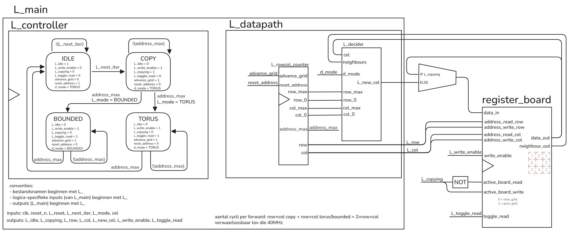
Each iteration consists of two phases tracked by L_controller. In the COPY phase, every cell from board0 is copied to board1. The L_rowcol_counter module scans through each cell sequentially, advancing to the next cell each clock cycle.
In the second phase, the next state of the grid is calculated based on board1 and written to board0. There are two variants of this phase, TORUS and BOUNDED. These refer to the two different ways to handle the edge of the grid. In BOUNDED, cells outside the grid are taken to be dead. In TORUS, the grid wraps around like a torus, so that for example above the top of the grid is the bottom of the grid.
Just like in the COPY phase, L_rowcol_counter will go over every cell. The L_decider module takes in the value of the current cell and its neighbours, and outputs L_new_cel based on the rules of Conway's Game of Life: a dead cell with three living neighbours comes alive, an alive cell with two or three alive neighbours stays alive, all other cell die or remain dead.
The logic architecture is illustrated below:
VGA
VGA (video graphics array) is an old technology, which means that it is easy to interface with. There are many different graphics modes, but this project has chosen the most common: 640x480@60Hz. The timing diagram is shown below.
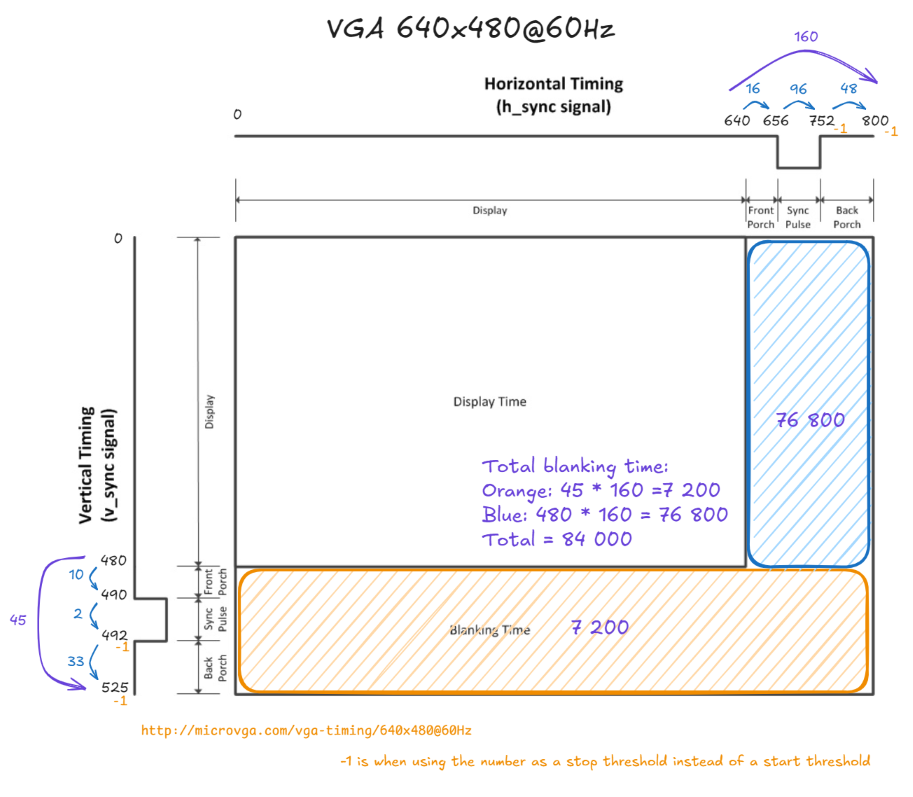
The beam will be scanning the screen from left to right, top to bottom. At the end of each scan line (640 pixels), a syncing pulse must be timed correctly. This is the hsync signal in the code. After 480 lines, a vertical sync pulse must be timed correctly. This is the vsync signal in the code. These signals are generated by the vga_hvsync_generator module. These signals are then used by the other vga modules to show the correct pixels to the screen at the correct time, based on the cell states saved in memory. The architecture for VGA is shown below.
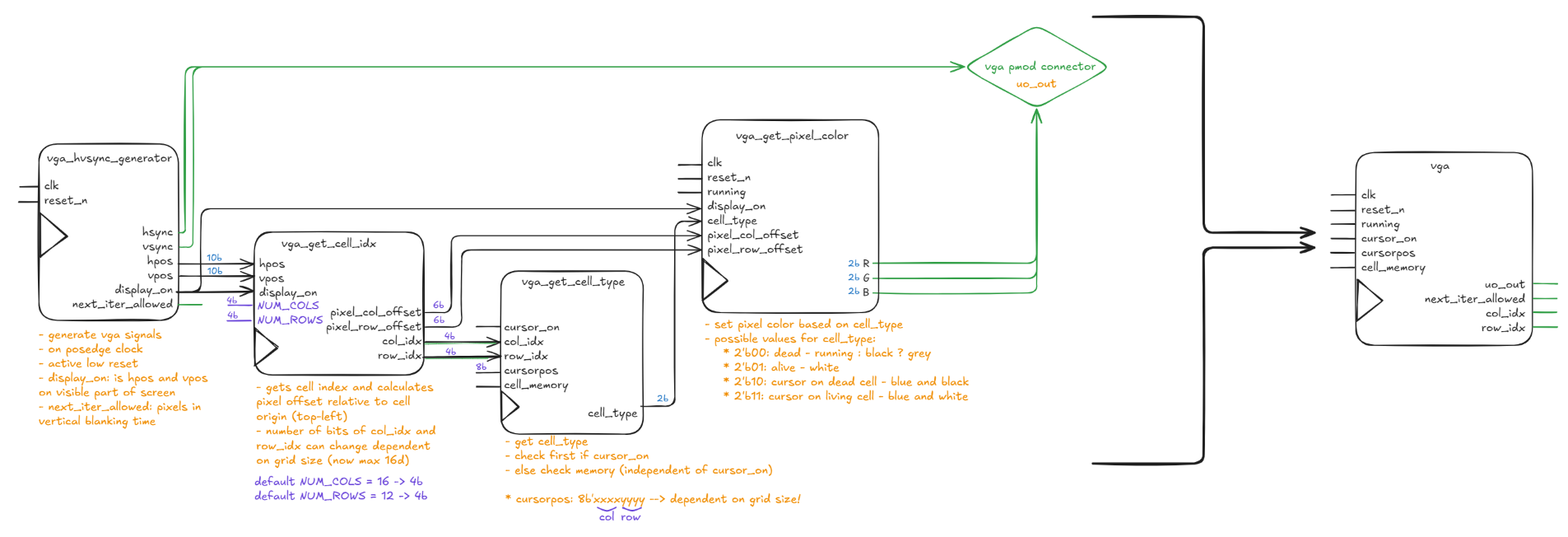
The vga_hvsync_generator not only generates hsync and vsync signals, but also keeps track of the horizontal and vertical position on the screen in pixels (hpos and vpos). These are later used by the vga_get_cell_idx module. When the scanning beam is in the viewable screen area (not in the blanking area), the display_on wire is set to 1, otherwise it is set to 0. When the scanning beam is in the orange part of the screen (vertical sync pulse, see diagram), next_iter_allowed is set to 1 to allow for the logic to generate the next iteration of the simulation.
The vga_get_cell_idx module calculates the coordinates of the current cell in the grid, based on the position of the pixel on the screen. In addition to the cell's col_idx/row_idx, it also outputs pixel_col_offset and pixel_row_offset, which indicate the pixel position within that cell. This info is later used to draw the cursor icon correctly.
The cell index that vga_get_cell_idx generates is used in the vga_get_cell_type module to determine the cell type. Unlike a single mutually-exclusive state, cell_type is made up of two independent bits: bit 0 reflects whether the cell is alive or dead (pulled from memory, board0), and bit 1 indicates whether the cursor is currently positioned on that cell. The cursor is only active when the user is editing the grid (cursor_on); when it overlaps a cell, that bit is set regardless of whether the underlying cell is alive or dead.
Based on the cell type, the simulation running state, and the pixel's offset within its cell, vga_get_pixel_color calculates the correct output color. Eacht color channel (RGB) has two bits, resulting in a 6 bit color pallete. When the cursor bit is set, the module only shows blue for pixels that fall inside a diamond-shaped icon (computed from pixel_col_offset/pixel_row_offset); pixels outside the diamond fall through to the normal alive/dead coloring for that cell. Note that dead cells are only shown as black while the simulation is running; when running is false, dead cells are shown as grey instead so a paused/stopped state is visually distinguishable.
| Description | cell_type (binary) | Pixel inside cursor icon | running | R | G | B | Color |
|---|---|---|---|---|---|---|---|
| dead | 00 |
— | 1 |
00 |
00 |
00 |
black |
| dead | 00 |
— | 0 |
10 |
10 |
10 |
grey |
| alive | 01 |
— | — | 11 |
11 |
11 |
white |
| cursor on dead cell | 10 |
yes | — | 00 |
00 |
11 |
blue |
| cursor on dead cell | 10 |
no | 1 |
00 |
00 |
00 |
black |
| cursor on dead cell | 10 |
no | 0 |
10 |
10 |
10 |
grey |
| cursor on alive cell | 11 |
yes | — | 00 |
00 |
11 |
blue |
| cursor on alive cell | 11 |
no | — | 11 |
11 |
11 |
white |
When testing, the TinyTapeout VGA trace visualizer from sylefeb proved to be very useful in visualising the VGA output from an .fst file.
The repository cocotb-vga from kul-tt2026 also proved invaluable when writing test benches for the entire project to visualise the VGA screen.
The VGA playground from Tiny Tapeout was incredible, because it could simulate in seconds what cocotb-vga took minutes. Click here for the link.
Connecting it all together
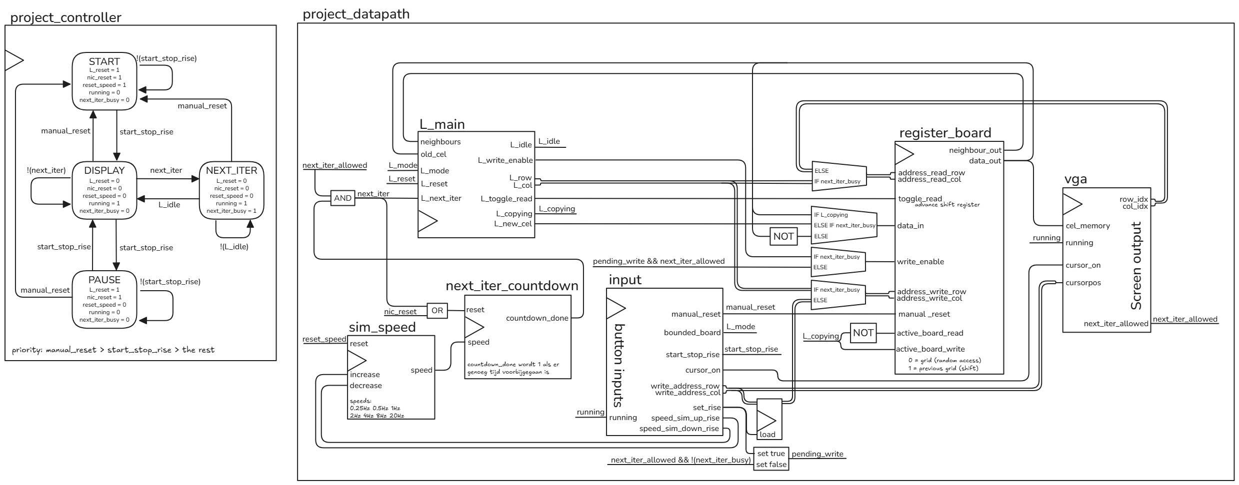
Everything is connected together with the project_controller and project_datapath modules. project_controller has four states: START, which can transition to DISPLAY, VGA's home territory. During NEXT_ITER, logic does its work and calculates the next state of the simulation. PAUSE is for when you want to take a closer look at what's happening.
It is important that the board doesn't change when VGA is still rendering the frame. Therefore, NEXT_ITER is only entered when VGA gives the next_iter_allowed signal. In a similar vein, input's actions only get written to memory when neither VGA nor logic is using it.
project_datapath connects all other modules together, and has some wiring to decide who can access the memory when. It also has the sim_speed and next_iter_countdown modules, which for given game speed that input can set counts down the time till a new NEXT_ITER can be started. The possible speeds are 0.25Hz, 0.5Hz, 1Hz, 2Hz, 4Hz, 8Hz and 20Hz. project_controller and project_datapath are best understood through the diagram below:
How to test
-
Clock speed 25.175 MHz.
-
Plug in the VGA Pmod connector.
-
Connect all 11 buttons (active high), pulled low.
-
Turn on the cursor (
ui_in[6]). -
Use the buttons to draw your own board. Use the move buttons (
ui_in[0-3]) to move the cursor, use the set button (ui_in[4]) to toggle a cell between dead and alive. -
Start with a glider or blinker.
Glider:
-------
.O.
..O
OOO
Blinker: -------- ..... ..O.. ..O.. ..O.. ..... -
Press play (
ui_in[5]) to start the simulation and let Conway's Game of Life come to life! -
Use the
uio_in[0]button to increase the simulation speed anduio_in[1]to decrease it. -
Reset everything by pulling manual reset (
uio_in[2]) high.
Note: uio_in[7] must be low to disable testing mode.
External hardware
- Tiny Tapeout VGA Pmod connector
- 11 buttons, active high with pull-down resistors
IO
| # | Input | Output | Bidirectional |
|---|---|---|---|
| 0 | button_up | R1 | button_speed_sim_up |
| 1 | button_down | G1 | button_speed_sim_down |
| 2 | button_left | B1 | button_reset |
| 3 | button_right | vsync | |
| 4 | button_set | R0 | |
| 5 | button_start_stop | G0 | |
| 6 | button_cursor_on_off | B0 | |
| 7 | button_bounded_board | hsync | testing |