845 Poly Synth v1.0
845 : Poly Synth v1.0
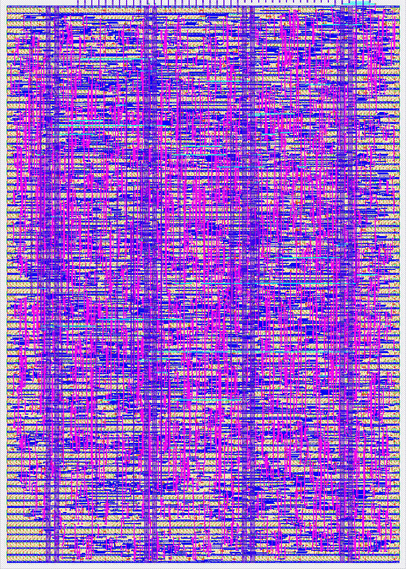
- Author: Colby Miller
- Description: Three-voice polyphonic DDS synthesizer with SPI control and 1-bit sigma-delta audio output.
- GitHub repository
- Open in 3D viewer
- Open in Tiny Tapeout Explorer
- Clock: 12000000 Hz
How It Works
This project is a three-voice polyphonic synthesizer. It works by implementing three direct digital synthesis (DDS) oscillators, called voices. The DDS oscillators are given tuning words, as well as config info. They accumulate and modify the signal, defining wave shape. The outputs from the three voices are summed together, and that result leaves the chip as a 1-bit sigma-delta bitstream. An external RC filter then turns that bitstream back into beautiful, buzzy audio.
  mosi ──┐
  sclk ──┤   ┌──────────────────┐
  cs_n ──┴──>│  spi_peripheral  │
             └───┬──────────┬───┘
       inc0/1/2  │          │  cfg0/1/2
        (32b)    │          │   (4b)
                 v          v
        ┌────────────────────────────┐
        │  dds0    dds1    dds2      │   phase_acc -> shaper
        └────┬───────┬───────┬───────┘
             │       │       │   signed [13:0]
             v       v       v
           ┌────────────────────┐
           │       mixer        │
           └─────────┬──────────┘
                     │ signed [15:0]
                     v
           ┌────────────────────┐
           │    sigma_delta     │
           └─────────┬──────────┘
                     │ 1-bit stream
                     v
                    out   -> external RC filter -> audio
Note: The synth features no ADSR or any other audio shaping, so expect artifacts while testing. I'm hoping to polish my design a bit more in v2.0.
Voices. Each voice has a 32-bit phase accumulator that adds a tuning word to itself every clock. The rate at which the accumulator wraps sets the pitch:
f_out = tuning_word * f_clk / 2^32
At the 12 MHz design clock that gives a frequency step of about 0.0028 Hz, so pitch error is far below one cent for any musical note. Middle C (261.63 Hz) is tuning word 93641; A4 (440 Hz) is 157482.
Waveform shaping. The top 14 bits of each accumulator are tapped and fed to a shaper that produces one of four waveforms:
| Wave Select | Output |
|---|---|
00 |
off (voice silent) |
01 |
sawtooth |
10 |
square (PWM) |
11 |
triangle |
For the square wave, a two-bit PWM field selects the duty cycle (12.5%, 25%, 50%, 75%) by comparing the phase tap against a threshold. The sawtooth is the phase tap passed straight through; the triangle is produced by folding the tap around its midpoint.
| PWM Select | Duty Value |
|---|---|
00 |
12.5% duty |
01 |
25% duty |
10 |
50% duty |
11 |
75% duty |
Mixing and output. The three signed 14-bit voice outputs are summed into a signed 16-bit mix bus, then converted to a 1-bit stream by a first-order sigma-delta modulator. The modulator is a 17-bit accumulator: the sample is converted from two's complement to offset binary (invert the MSB), added to the running remainder each clock, and the carry out of the accumulator is the output bit. The density of 1s in that stream encodes the audio level, so the output pin toggles continuously even when the synth is idle.
Because the modulator runs at the full system clock against the audio signal, the oversampling ratio is in the hundreds. That pushes the unwanted noise far above the threshold of hearing, which is why a single-pole RC filter is enough to recover a clean tone.
Control. All parameters are set over SPI. Frames are 35 bits: a 3-bit address followed by 32 bits of data, MSB first, SPI mode 0 (clock idles low, data sampled on the rising edge). The frame commits on the rising edge of chip select, and only if exactly 35 bits were received. Anything else just gets thrown away.
| Address | Register | Contents |
|---|---|---|
| 0 | inc0 |
voice 0 tuning word (32 bits) |
| 1 | inc1 |
voice 1 tuning word (32 bits) |
| 2 | inc2 |
voice 2 tuning word (32 bits) |
| 3 | cfg0 |
voice 0 config: [3:2] wave select, [1:0] PWM width |
| 4 | cfg1 |
voice 1 config |
| 5 | cfg2 |
voice 2 config |
| 6, 7 | X | unused, writes ignored |
Registers hold their values indefinitely, so a note sustains until it is
overwritten. Writing a tuning word of zero freezes that voice's accumulator, which
silences it. If you want it to function as a traditional synthesizer, make sure to send
empty tuning words to the voice after you are done playing a note, or by setting wave select to 00.
SCLK is asynchronous to the system clock, so it is brought into the chip's clock domain through two-flop synchronisers plus edge detection. This costs a few clocks per SPI edge and sets the maximum SCLK rate (see below). For this use case, the overhead is plenty.
How to Test
Timing limits. SCLK must not exceed one sixth of the system clock — at 12 MHz that is a 2 MHz ceiling. Each SCLK phase (high and low) must last at least three system clocks. Hold chip select low for a few system clocks after the final SCLK edge before releasing it, so the bit counter settles before the frame commits.
Making a sound. Send two frames:
- Address 3, data
0x0000000C— sets voice 0 to a triangle wave. - Address 0, data
0x00016DC9(93641) — plays middle C on voice 0.
The audio bitstream appears on uo_out[0]. Filter it (see below) and the tone is
audible immediately. Send address 0 with data 0 to silence the voice, or set the wave select to 00.
As a side note, they will both probably click, but they'll click differently, pick whichever you find less abrasive.
For chords, load different tuning words into addresses 1 and 2 with their configs at addresses 4 and 5.
Without a filter, uo_out[0] is a 1-bit stream at the full clock rate. You can
verify the chip is alive by watching the pin toggle, or by capturing the stream and
measuring the density of 1s: a constant density means a constant level, and a
density that varies periodically is your waveform.
Clock. The design assumes 12 MHz. It will run at other frequencies, but all pitches scale proportionally — recompute tuning words with the formula above. The design is entirely agnostic to the tuning word and the frequency.
External Hardware
Reconstruction filter (required to hear anything). A single RC low-pass on
uo_out[0] with a corner above the audio band is sufficient. 1 kΩ and 6.8 nF
gives a corner around 23 kHz. A second identical RC stage in series drops the
residual noise further, but is not necessary in practice.
DC blocking capacitor (required). The filtered signal sits at roughly mid-rail, not at ground. Put a series capacitor of 1 µF or more between the filter output and whatever you are driving, or you will feed DC into it.
Output. The coupled signal drives a line input directly, or high-impedance headphones (tested working with 300 Ω headphones straight off the filter while testing with FPGA). Low impedance headphones or a speaker need a small audio amplifier. Volume is also handled off-chip, so adding something like a potentiometer set up as a v-divider should work great.
SPI controller. Any microcontroller that can bit-bang or drive 35-bit SPI frames within the timing limits above. The demo board's RP2040 should get the job done just fine.
uo_out[0] ──[1kΩ]──┬──[1µF]── audio out
                   │
                  6.8nF
                   │
                  GND
IO
| # | Input | Output | Bidirectional |
|---|---|---|---|
| 0 | MOSI | Audio | |
| 1 | SCLK | ||
| 2 | CS_N | ||
| 3 | |||
| 4 | |||
| 5 | |||
| 6 | |||
| 7 |