Configuring and flashing the QSPI Pmod
This guide will cover configuring third-party produced QSPI Pmods. You do not need to follow the configuration steps if you have purchased one from the Tiny Tapeout store.
The steps required for flashing the Pmods remain identical between the first-party and third-party ones, and therefore the flashing portion of this guide applies to both types.
The first-party QSPI Pmod is only compatible with TT04 and later demoboards.
Configuring Quad SPI mode
This mode is enabled by default on all first-party QSPI Pmods. You should not need to configure this yourself unless you have changed the configuration previously.
The flash chip used on the QSPI Pmod is the 25Q128JVSM, a part of the Winbond W25Q128JV family of flash memories. The
datasheet (page 16) states that the
QUAD ENABLE bit must be set in order to activate the quad SPI mode of the flash.
To do so, we can use a MicroPython script running on the demoboard to configure the memory. To begin, plug in your
QSPI Pmod to the BIDIR Pmod header on the demoboard.
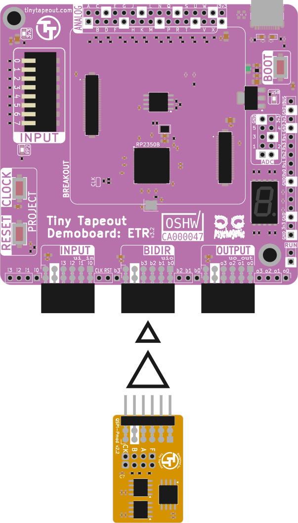
Plugging in the QSPI Pmod to the bidirectional port of the ETR demoboard
-
Connect your demoboard to your PC.
-
Go to the Tiny Tapeout Commander, click the “CONNECT TO BOARD” button and select your demoboard from the prompt.

Tiny Tapeout Commander page with the "CONNECT TO BOARD" button
This step requires WebSerial - it is currently not supported by Firefox. You will need a Chromium-based browser.
A window should appear asking you to select your board.
- Select your board and click “Connect”.
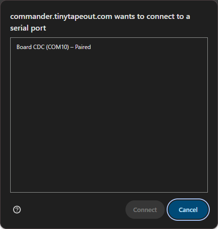
Tiny Tapeout Commander asking for permission to connect to a board
- Once connected, select the chip ROM project (address 0) and then navigate to the “REPL” tab
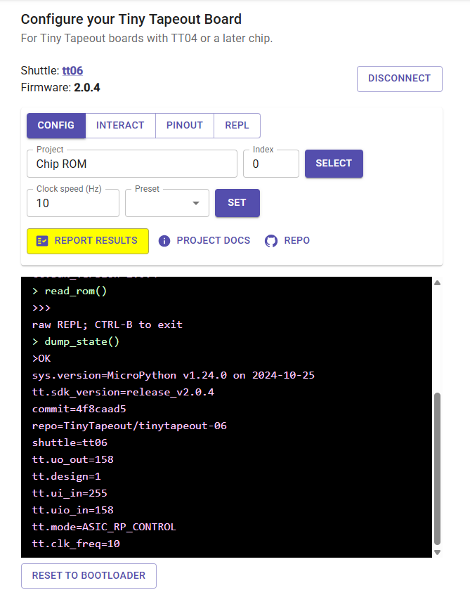
Tiny Tapeout Commander configuration/interface page
The REPL tab gives you access to the MicroPython instance that is running on the demoboard. Among other things, it allows you to enter code and run custom scripts.
Basic controls for REPL:
- Ctrl + E: enter paste mode
- Ctrl + Shift + V: paste clipboard
- Ctrl + D: exit paste mode
With the Pmod connected to the demoboard and access to the REPL, we can now configure the QSPI mode for the chip. The section you need to follow next will depend on the version of the demoboard you are using: follow the ETR section if you have an ETR demoboard, or the legacy section if you have a demoboard intended for TT04+.
Using an ETR Demoboard
- Copy the ETR-compatible QSPI activation script provided at the end of this guide.
- Enter paste mode in the commander.
- Paste the entirety of the script into the REPL.
- Exit paste mode, let the script do the job.
- Hit Ctrl + C to exit the serial bridge and go back to REPL.
If successful, you should see an output similar to the figure below.
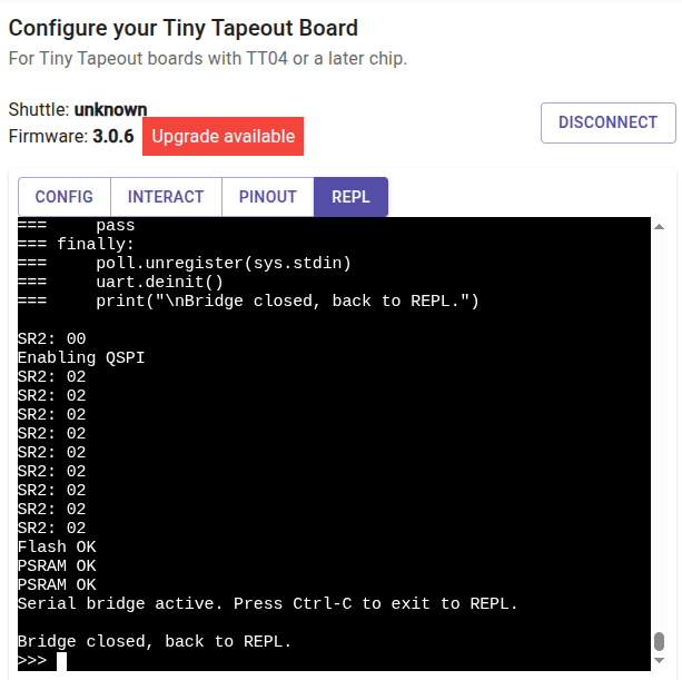
Successfully executing the activation script and enabling QSPI mode
Using a Legacy Demoboard
- Copy the Old Demoboard based QSPI activation script provided at the end of this guide.
- Enter paste mode in the commander.
- Paste the entirety of the script into the REPL.
- Exit paste mode and press enter.
- In the MicroPython prompt, type
run_test()and press enter to execute it.
If successful, you should see an output similar to the figure below.
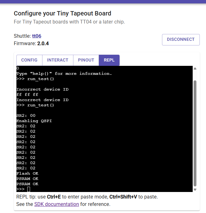
Successfully executing the activation script and enabling QSPI mode
Congratulations! You should now be ready to write some data to the flash - you can proceed to the next section.
Flashing your QSPI Pmod
- Go to the Tiny Tapeout Flasher, click the “CONNECT TO BOARD” button and select your demoboard from the prompt.
You may have to connect from the Commander first.
If you were following the “Configuring QUAD SPI mode” section, you should pay attention to
the reported “Flash ID” on the website. It should have changed from 000000 to ef7018. If not, you may need to repeat
the previous section and double check your wiring.
- Select your own
.binto flash, or pick one of the provided firmware to flash to your Pmod.
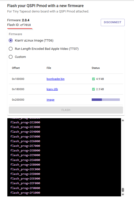
Tiny Tapeout Flasher page showing available images and terminal output
You can continue to use the QSPI memory as either a 1-bit or 4-bit interface depending on the design requirements.
Congratulations! You should now have a QSPI Pmod flashed with a firmware image, ready for you to use with a design of your choice.
Appendix
1. Legacy Demoboard-compatible QSPI Activation Script
This script is provided by Diego Satizabal (github.com/dsatizabal). Copy to your clipboard by clicking the clipboard button top right of the code block.
import time
import machine
import gc
import random
import rp2
from machine import SPI, Pin
from time import sleep_ms

mux_sel = Pin(1, Pin.OUT)
mux_sel.on()
led_segs = [Pin(5, Pin.OUT), Pin(6, Pin.OUT), Pin(7, Pin.OUT), Pin(8, Pin.OUT),
            Pin(13, Pin.OUT), Pin(14, Pin.OUT), Pin(15, Pin.OUT), Pin(16, Pin.OUT)]

def clear():
    for led in led_segs:
        led.off()

pass_text = [[1, 1, 0, 0, 1, 1, 1, 0], [1, 1, 1, 0, 1, 1, 1, 0], [1, 0, 1, 1, 0, 1, 1, 0], [1, 0, 1, 1, 0, 1, 1, 1]]
fail_text = [[1, 0, 0, 0, 1, 1, 1, 0], [1, 1, 1, 0, 1, 1, 1, 0], [0, 1, 1, 0, 0, 0, 0, 0], [0, 0, 0, 1, 1, 1, 0, 1]]

def display_text(text, reps):
    for r in range(reps):
        for char in text:
            for i in range(8):
                led_segs[i].value(char[i])
            sleep_ms(250)
        sleep_ms(250)

def display_pass(reps = 3):
    display_text(pass_text, reps)

def display_fail(reps = 3):
    display_text(fail_text, reps)

# Set this to false if no TT carrier is mounted on the demoboard
DISABLE_TT_ASIC = False

# Set this to false when testing the QSPI Pmod mounted in the audio Pmod
TEST_RAM_B = True

if DISABLE_TT_ASIC:
    from ttboard.mode import RPMode
    from ttboard.demoboard import DemoBoard

@rp2.asm_pio(out_shiftdir=0, autopull=True, pull_thresh=8, autopush=True, push_thresh=8, sideset_init=(rp2.PIO.OUT_LOW,), out_init=rp2.PIO.OUT_LOW)
def spi_cpha0():
    out(pins, 1)             .side(0x0)
    in_(pins, 1)             .side(0x1)

@rp2.asm_pio(autopush=True, push_thresh=8, in_shiftdir=rp2.PIO.SHIFT_LEFT,
             autopull=True, pull_thresh=8, out_shiftdir=rp2.PIO.SHIFT_RIGHT,
             out_init=(rp2.PIO.OUT_HIGH, rp2.PIO.OUT_HIGH, rp2.PIO.IN_HIGH, rp2.PIO.IN_HIGH,
                       rp2.PIO.IN_HIGH, rp2.PIO.IN_HIGH, rp2.PIO.OUT_HIGH, rp2.PIO.OUT_HIGH),
             sideset_init=(rp2.PIO.OUT_HIGH))
def qspi_read():
    out(x, 8).side(1)
    out(y, 32).side(1)
    out(pindirs, 8).side(1)

    label("cmd_loop")
    out(pins, 8).side(0)
    jmp(x_dec, "cmd_loop").side(1)

    out(pindirs, 8).side(0)
    label("data_loop")
    in_(pins, 8).side(1)
    jmp(y_dec, "data_loop").side(0)

    out(pins, 8).side(1)
    out(pindirs, 8).side(1)

class PIOSPI:

    def __init__(self, sm_id, pin_mosi, pin_miso, pin_sck, freq=1000000):
        self._sm = rp2.StateMachine(sm_id, spi_cpha0, freq=2*freq, sideset_base=Pin(pin_sck), out_base=Pin(pin_mosi), in_base=Pin(pin_miso))
        self._sm.active(1)

    @micropython.native
    def write(self, wdata):
        first = True
        for b in wdata:
            self._sm.put(b, 24)
            if not first:
                self._sm.get()
            else:
                first = False
        self._sm.get()

    def read(self, n):
        return self.write_read_blocking([0,]*n)

    @micropython.native
    def readinto(self, rdata):
        self._sm.put(0)
        for i in range(len(rdata)-1):
            self._sm.put(0)
            rdata[i] = self._sm.get()
        rdata[-1] = self._sm.get()

    @micropython.native
    def write_read_blocking(self, wdata):
        rdata = bytearray(len(wdata))
        i = -1
        for b in wdata:
            self._sm.put(b, 24)
            if i >= 0:
                rdata[i] = self._sm.get()
            i += 1
        rdata[i] = self._sm.get()
        return rdata

def flash_program(test_data, addr=0):
    flash_sel = Pin(21, Pin.OUT)
    flash_sel.on()
    spi = PIOSPI(1, Pin(22), Pin(23), Pin(24), freq=10000000)

    ram_a_sel = Pin(27, Pin.OUT)
    ram_b_sel = Pin(28, Pin.OUT)

    flash_sel.on()
    ram_a_sel.on()
    ram_b_sel.on()

    flash_wp = Pin(25, Pin.IN, Pin.PULL_UP)
    flash_hold = Pin(26, Pin.IN, Pin.PULL_UP)

    def flash_cmd(data, dummy_len=0, read_len=0):
        dummy_buf = bytearray(dummy_len)
        read_buf = bytearray(read_len)

        flash_sel.off()
        spi.write(bytearray(data))
        if dummy_len > 0:
            spi.readinto(dummy_buf)
        if read_len > 0:
            spi.readinto(read_buf)
        flash_sel.on()

        return read_buf

    def flash_cmd2(data, data2):
        flash_sel.off()
        spi.write(bytearray(data))
        spi.write(data2)
        flash_sel.on()

    def print_bytes(data):
        for b in data: print("%02x " % (b,), end="")
        print()

    CMD_WRITE = 0x02
    CMD_READ = 0x03
    CMD_READ_SR1 = 0x05
    CMD_READ_SR2 = 0x35
    CMD_WRITE_SR2 = 0x31
    CMD_WEN = 0x06
    CMD_SECTOR_ERASE = 0x20
    CMD_ID  = 0x90
    CMD_LEAVE_CM = 0xFF

    flash_cmd([CMD_LEAVE_CM])
    id = flash_cmd([CMD_ID], 2, 3)
    if id[1] != 0xef or id[2] != 0x17:
        print("Incorrect device ID")
        print_bytes(id)
        raise Exception("Incorrect device ID")

    sr2 = flash_cmd([CMD_READ_SR2], 0, 1)[0]
    print(f"SR2: {sr2:02x}")
    if (sr2 & 2) == 0:
        print("Enabling QSPI")
        flash_cmd([CMD_WEN])
        flash_cmd2([CMD_WRITE_SR2], [2])
        time.sleep(0.01)

    offset = 0
    sector = addr // 4096
    while True:
        num_bytes = min(len(test_data) - offset, 4096)
        if num_bytes <= 0:
            break

        flash_cmd([CMD_WEN])
        flash_cmd([CMD_SECTOR_ERASE, sector >> 4, (sector & 0xF) << 4, 0])

        while flash_cmd([CMD_READ_SR1], 0, 1)[0] & 1:
            #print("*", end="")
            time.sleep(0.001)
        #print(".", end="")

        for i in range(0, num_bytes, 256):
            flash_cmd([CMD_WEN])
            idx = i + offset
            flash_cmd2([CMD_WRITE, sector >> 4, ((sector & 0xF) << 4) + (i >> 8), 0], test_data[idx:min(idx+256, num_bytes)])

            while flash_cmd([CMD_READ_SR1], 0, 1)[0] & 1:
                #print("-", end="")
                time.sleep(0.001)
        sector += 1
        offset += num_bytes
        #print(f". {sector*4}kB")

    #print("Program done")

    i = addr // 256
    offset = 0
    while True:
        num_bytes = min(len(test_data) - offset, 256)
        if num_bytes <= 0:
            break

        data_from_flash = flash_cmd([CMD_READ, i >> 8, i & 0xFF, 0], 0, num_bytes)
        for j in range(num_bytes):
            if test_data[offset+j] != data_from_flash[j]:
                raise Exception(f"Error at {i:02x}:{j:02x}: {test_data[offset+j]} != {data_from_flash[j]}")
        i += 1
        offset += num_bytes

    spi._sm.active(0)
    del spi

def flash_test_qspi(test_data, addr):
    sm = rp2.StateMachine(1, qspi_read, 16_000_000, in_base=Pin(21), out_base=Pin(21), sideset_base=Pin(24))
    sm.active(1)

    def fmt_addr_nibble(n):
        return 0b11000000 | ((n & 0xc) << 2) | ((n & 3) << 1)

    def read_data_enable_cm(num_bytes, addr):
        buf = bytearray(num_bytes)

        sm.put(8+6+2-1)     # Command + Address + Dummy - 1
        sm.put(num_bytes*2 + 4 - 1) # Data + Dummy - 1
        sm.put(0b11111111)  # Directions

        sm.put(0b11000010)  # Command
        sm.put(0b11000010)  # RAM_B_SEL, RAM_A_SEL, SD3, SD2, SCK, SD1, SD0, CS
        sm.put(0b11000010)
        sm.put(0b11000000)
        sm.put(0b11000010)
        sm.put(0b11000000)
        sm.put(0b11000010)
        sm.put(0b11000010)

        sm.put(fmt_addr_nibble(addr >> 20))  # Address
        sm.put(fmt_addr_nibble(addr >> 16))
        sm.put(fmt_addr_nibble(addr >> 12))
        sm.put(fmt_addr_nibble(addr >> 8))
        sm.put(fmt_addr_nibble(addr >> 4))
        sm.put(fmt_addr_nibble(addr))
        sm.put(0b11100100) # RAM_B_SEL, RAM_A_SEL, SD3, SD2, SCK, SD1, SD0, CS
        sm.put(0b11100100)

        sm.put(0b11001001)  # Directions

        for i in range(4):
            sm.get()

        for i in range(num_bytes):
            h = sm.get()
            l = sm.get()
            buf[i] = ((h & 0x30) << 2) | ((h & 0x6) << 3) | ((l & 0x30) >> 2) | ((l & 0x6) >> 1)

        sm.put(0b11111111)
        sm.put(0b11001011)  # Directions

        return buf

    def read_data_cm(num_bytes, addr, exit_cm=False):
        buf = bytearray(num_bytes)

        sm.put(6+2-1)     # Address + Dummy - 1
        sm.put(num_bytes*2 + 4 - 1) # Data + Dummy - 1
        sm.put(0b11111111)  # Directions

        sm.put(fmt_addr_nibble(addr >> 20))  # Address
        sm.put(fmt_addr_nibble(addr >> 16))
        sm.put(fmt_addr_nibble(addr >> 12))
        sm.put(fmt_addr_nibble(addr >> 8))
        sm.put(fmt_addr_nibble(addr >> 4))
        sm.put(fmt_addr_nibble(addr))
        if exit_cm:
            sm.put(0b11110110) # SD3, RAM_B_SEL, SD2, RAM_A_SEL, SD0, SCK, CS, SD1
            sm.put(0b11110110)
        else:
            sm.put(0b11100100) # RAM_B_SEL, RAM_A_SEL, SD3, SD2, SCK, SD1, SD0, CS
            sm.put(0b11100100)

        sm.put(0b11001001)  # Directions

        for i in range(4):
            sm.get()

        for i in range(num_bytes):
            h = sm.get()
            l = sm.get()
            buf[i] = ((h & 0x30) << 2) | ((h & 0x6) << 3) | ((l & 0x30) >> 2) | ((l & 0x6) >> 1)

        sm.put(0b11111111)
        sm.put(0b11001011)  # Directions

        return buf

    num_bytes = 256
    offset = 0
    data_from_flash = read_data_enable_cm(num_bytes, addr)
    for j in range(num_bytes):
        if test_data[j+offset] != data_from_flash[j]:
            raise Exception(f"Error at {addr:02x}:{j:02x}: {test_data[j+offset]} != {data_from_flash[j]}")
    offset += num_bytes

    for i in range(num_bytes, 1024, num_bytes):
        data_from_flash = read_data_cm(num_bytes, addr+i)
        for j in range(num_bytes):
            if test_data[j+offset] != data_from_flash[j]:
                raise Exception(f"Error at {addr+i:02x}:{j:02x}: {test_data[j+offset]} != {data_from_flash[j]}")
        offset += num_bytes

    data_from_flash = read_data_cm(num_bytes, addr+1024, True)
    for j in range(num_bytes):
        if test_data[j+offset] != data_from_flash[j]:
            raise Exception(f"Error at {addr+i:02x}:{j:02x}: {test_data[j+offset]} != {data_from_flash[j]}")

    sm.active(0)
    del sm

def test_psram(use_ram_b=True):
    flash_sel = Pin(21, Pin.OUT)
    flash_sel.on()
    spi = PIOSPI(1, Pin(22), Pin(23), Pin(24), freq=10000000)

    ram_a_sel = Pin(27, Pin.OUT)
    ram_b_sel = Pin(28, Pin.OUT)

    flash_sel.on()
    ram_a_sel.on()
    ram_b_sel.on()

    CMD_WRITE = 0x02
    CMD_READ = 0x03

    def spi_cmd(data, sel, dummy_len=0, read_len=0):
        dummy_buf = bytearray(dummy_len)
        read_buf = bytearray(read_len)

        sel.off()
        spi.write(bytearray(data))
        if dummy_len > 0:
            spi.readinto(dummy_buf)
        if read_len > 0:
            spi.readinto(read_buf)
        sel.on()

        return read_buf

    def spi_cmd2(data, data2, sel):
        sel.off()
        spi.write(bytearray(data))
        spi.write(data2)
        sel.on()

    buf = bytearray(8)

    ram_set = [ram_a_sel,]
    if use_ram_b:
        ram_set.append(ram_b_sel)

    for ram in ram_set:
        for j in range(1024):
            addr = random.randint(0, 8 * 1024 * 1024 - 8)
            for i in range(8):
                buf[i] = random.randint(0, 255)

            spi_cmd2([CMD_WRITE, addr >> 16, (addr >> 8) & 0xFF, addr & 0xFF], buf, ram)
            data = spi_cmd([CMD_READ, addr >> 16, (addr >> 8) & 0xFF, addr & 0xFF], ram, 0, 8)

            for i in range(8):
                if buf[i] != data[i]:
                    raise Exception(f"Error {buf[i]} != {data[i]} at addr {addr}+{i}")

        print("PSRAM OK")


def disable_tt_board():
    if DISABLE_TT_ASIC:
        # Select the chip ROM, which should always be present and set the bidirs to all inputs
        # so we can drive them with SPI
        tt = DemoBoard()
        tt.shuttle.tt_um_chip_rom.enable()

def test_flash(iters = 1):
    gc.collect()
    test_len = 2000
    test_data = bytearray(test_len)
    for j in range(iters):
        for i in range(test_len):
            test_data[i] = random.randint(0, 255)
        addr = 4096*random.randint(0, random.randint(0,4092))
        #print(f"Program at {addr:x}")
        flash_program(test_data, addr)
        flash_test_qspi(test_data, addr)
        gc.collect()
    print("Flash OK")

def run_test():
    disable_tt_board()
    print()
    try:
        test_flash(10)
        test_psram(TEST_RAM_B)
    except Exception as e:
        print(e)
        display_fail()
    else:
        display_pass()

import uselect
import sys
from machine import UART


uart = UART(0, baudrate=115200, tx=tt.pins.ui_in3.raw_pin, rx=tt.pins.uo_out4.raw_pin)
poll = uselect.poll()
poll.register(sys.stdin, uselect.POLLIN)


while True:
    if poll.poll(0):
        _ = uart.write(sys.stdin.buffer.read(1))
    uart_data = uart.read()
    if uart_data:
        _ = sys.stdout.write(uart_data)
2. ETR-compatible QSPI Activation Script
This script is provided by Rohan Verma (github.com/rohanverm94). Copy to your clipboard by clicking the clipboard button top right of the code block.
import time
import machine
import gc
import random
import rp2
from machine import SPI, Pin
from time import sleep_ms

# RP2350: pin the system clock so PIO dividers resolve to deterministic rates.
machine.freq(150_000_000)

# ---------------------------------------------------------------------------
# TT ETR demoboard (RP2350B) QSPI Pmod routing.
#
# On this board the bidirectional Pmod (uio[0..7]) is wired to GPIO25..GPIO32,
# i.e. the original RP2040 base (GPIO21..28) shifted up by 4. The logical
# Pmod line order is unchanged, so every pin is just (original + 4) and the
# PIO programs / bit-packing constants remain valid.
#
#   uio[0] GPIO25  CS0 / Flash      (orig 21)
#   uio[1] GPIO26  SD0 / MOSI       (orig 22)
#   uio[2] GPIO27  SD1 / MISO       (orig 23)
#   uio[3] GPIO28  SCK              (orig 24)  <- sideset base = QSPI_BASE+3
#   uio[4] GPIO29  SD2 (was WP)     (orig 25)
#   uio[5] GPIO30  SD3 (was HOLD)   (orig 26)
#   uio[6] GPIO31  CS1 / RAM A      (orig 27)
#   uio[7] GPIO32  CS2 / RAM B      (orig 28)  <- crosses into pad bank 1
#
# NOTE: GPIO32 is in pad bank 1 (bank 0 = GPIO0-31). PIO drives across the
# boundary fine because the GPIO offsets are still consecutive from the base.
# ---------------------------------------------------------------------------
QSPI_BASE = 25            # uio[0] GPIO number; was 21 on the RP2040 demoboard
PIN_FLASH_CS = QSPI_BASE + 0   # 25
PIN_MOSI     = QSPI_BASE + 1   # 26
PIN_MISO     = QSPI_BASE + 2   # 27
PIN_SCK      = QSPI_BASE + 3   # 28
PIN_SD2      = QSPI_BASE + 4   # 29  (formerly flash WP)
PIN_SD3      = QSPI_BASE + 5   # 30  (formerly flash HOLD)
PIN_RAM_A_CS = QSPI_BASE + 6   # 31
PIN_RAM_B_CS = QSPI_BASE + 7   # 32

mux_sel = Pin(1, Pin.OUT)
mux_sel.on()
led_segs = [Pin(5, Pin.OUT), Pin(6, Pin.OUT), Pin(7, Pin.OUT), Pin(8, Pin.OUT),
            Pin(13, Pin.OUT), Pin(14, Pin.OUT), Pin(15, Pin.OUT), Pin(16, Pin.OUT)]
def clear():
    for led in led_segs:
        led.off()
pass_text = [[1, 1, 0, 0, 1, 1, 1, 0], [1, 1, 1, 0, 1, 1, 1, 0], [1, 0, 1, 1, 0, 1, 1, 0], [1, 0, 1, 1, 0, 1, 1, 1]]
fail_text = [[1, 0, 0, 0, 1, 1, 1, 0], [1, 1, 1, 0, 1, 1, 1, 0], [0, 1, 1, 0, 0, 0, 0, 0], [0, 0, 0, 1, 1, 1, 0, 1]]
def display_text(text, reps):
    for r in range(reps):
        for char in text:
            for i in range(8):
                led_segs[i].value(char[i])
            sleep_ms(250)
        sleep_ms(250)
def display_pass(reps = 3):
    display_text(pass_text, reps)

def display_fail(reps = 3):
    display_text(fail_text, reps)
# Set this to false if no TT carrier is mounted on the demoboard
DISABLE_TT_ASIC = False
# Set this to false when testing the QSPI Pmod mounted in the audio Pmod
TEST_RAM_B = True
if DISABLE_TT_ASIC:
    from ttboard.mode import RPMode
    from ttboard.demoboard import DemoBoard

@rp2.asm_pio(out_shiftdir=0, autopull=True, pull_thresh=8, autopush=True, push_thresh=8, sideset_init=(rp2.PIO.OUT_LOW,), out_init=rp2.PIO.OUT_LOW)
def spi_cpha0():
    out(pins, 1)             .side(0x0)
    in_(pins, 1)             .side(0x1)
@rp2.asm_pio(autopush=True, push_thresh=8, in_shiftdir=rp2.PIO.SHIFT_LEFT,
             autopull=True, pull_thresh=8, out_shiftdir=rp2.PIO.SHIFT_RIGHT,
             out_init=(rp2.PIO.OUT_HIGH, rp2.PIO.OUT_HIGH, rp2.PIO.IN_HIGH, rp2.PIO.IN_HIGH,
                       rp2.PIO.IN_HIGH, rp2.PIO.IN_HIGH, rp2.PIO.OUT_HIGH, rp2.PIO.OUT_HIGH),
             sideset_init=(rp2.PIO.OUT_HIGH))
def qspi_read():
    out(x, 8).side(1)
    out(y, 32).side(1)
    out(pindirs, 8).side(1)

    label("cmd_loop")
    out(pins, 8).side(0)
    jmp(x_dec, "cmd_loop").side(1)

    out(pindirs, 8).side(0)
    label("data_loop")
    in_(pins, 8).side(1)
    jmp(y_dec, "data_loop").side(0)

    out(pins, 8).side(1)
    out(pindirs, 8).side(1)
class PIOSPI:
    def __init__(self, sm_id, pin_mosi, pin_miso, pin_sck, freq=1000000):
        self._sm = rp2.StateMachine(sm_id, spi_cpha0, freq=2*freq, sideset_base=Pin(pin_sck), out_base=Pin(pin_mosi), in_base=Pin(pin_miso))
        self._sm.active(1)
    @micropython.native
    def write(self, wdata):
        first = True
        for b in wdata:
            self._sm.put(b, 24)
            if not first:
                self._sm.get()
            else:
                first = False
        self._sm.get()

    def read(self, n):
        return self.write_read_blocking([0,]*n)
    @micropython.native
    def readinto(self, rdata):
        self._sm.put(0)
        for i in range(len(rdata)-1):
            self._sm.put(0)
            rdata[i] = self._sm.get()
        rdata[-1] = self._sm.get()
    @micropython.native
    def write_read_blocking(self, wdata):
        rdata = bytearray(len(wdata))
        i = -1
        for b in wdata:
            self._sm.put(b, 24)
            if i >= 0:
                rdata[i] = self._sm.get()
            i += 1
        rdata[i] = self._sm.get()
        return rdata
def flash_program(test_data, addr=0):
    flash_sel = Pin(PIN_FLASH_CS, Pin.OUT)
    flash_sel.on()
    spi = PIOSPI(1, Pin(PIN_MOSI), Pin(PIN_MISO), Pin(PIN_SCK), freq=10000000)
    ram_a_sel = Pin(PIN_RAM_A_CS, Pin.OUT)
    ram_b_sel = Pin(PIN_RAM_B_CS, Pin.OUT)
    flash_sel.on()
    ram_a_sel.on()
    ram_b_sel.on()

    # SD2 / SD3 (formerly flash WP / HOLD). Held high via pull-ups while in
    # single-SPI mode so the flash isn't write-protected / held.
    flash_wp = Pin(PIN_SD2, Pin.IN, Pin.PULL_UP)
    flash_hold = Pin(PIN_SD3, Pin.IN, Pin.PULL_UP)
    def flash_cmd(data, dummy_len=0, read_len=0):
        dummy_buf = bytearray(dummy_len)
        read_buf = bytearray(read_len)

        flash_sel.off()
        spi.write(bytearray(data))
        if dummy_len > 0:
            spi.readinto(dummy_buf)
        if read_len > 0:
            spi.readinto(read_buf)
        flash_sel.on()

        return read_buf
    def flash_cmd2(data, data2):
        flash_sel.off()
        spi.write(bytearray(data))
        spi.write(data2)
        flash_sel.on()
    def print_bytes(data):
        for b in data: print("%02x " % (b,), end="")
        print()
    CMD_WRITE = 0x02
    CMD_READ = 0x03
    CMD_READ_SR1 = 0x05
    CMD_READ_SR2 = 0x35
    CMD_WRITE_SR2 = 0x31
    CMD_WEN = 0x06
    CMD_SECTOR_ERASE = 0x20
    CMD_ID  = 0x90
    CMD_LEAVE_CM = 0xFF
    flash_cmd([CMD_LEAVE_CM])
    id = flash_cmd([CMD_ID], 2, 3)
    if id[1] != 0xef or id[2] != 0x17:
        print("Incorrect device ID")
        print_bytes(id)
        raise Exception("Incorrect device ID")
    sr2 = flash_cmd([CMD_READ_SR2], 0, 1)[0]
    print(f"SR2: {sr2:02x}")
    if (sr2 & 2) == 0:
        print("Enabling QSPI")
        flash_cmd([CMD_WEN])
        flash_cmd2([CMD_WRITE_SR2], [2])
        time.sleep(0.01)

    offset = 0
    sector = addr // 4096
    while True:
        num_bytes = min(len(test_data) - offset, 4096)
        if num_bytes <= 0:
            break

        flash_cmd([CMD_WEN])
        flash_cmd([CMD_SECTOR_ERASE, sector >> 4, (sector & 0xF) << 4, 0])
        while flash_cmd([CMD_READ_SR1], 0, 1)[0] & 1:
            #print("*", end="")
            time.sleep(0.001)
        #print(".", end="")
        for i in range(0, num_bytes, 256):
            flash_cmd([CMD_WEN])
            idx = i + offset
            flash_cmd2([CMD_WRITE, sector >> 4, ((sector & 0xF) << 4) + (i >> 8), 0], test_data[idx:min(idx+256, num_bytes)])
            while flash_cmd([CMD_READ_SR1], 0, 1)[0] & 1:
                #print("-", end="")
                time.sleep(0.001)
        sector += 1
        offset += num_bytes
        #print(f". {sector*4}kB")

    #print("Program done")
    i = addr // 256
    offset = 0
    while True:
        num_bytes = min(len(test_data) - offset, 256)
        if num_bytes <= 0:
            break

        data_from_flash = flash_cmd([CMD_READ, i >> 8, i & 0xFF, 0], 0, num_bytes)
        for j in range(num_bytes):
            if test_data[offset+j] != data_from_flash[j]:
                raise Exception(f"Error at {i:02x}:{j:02x}: {test_data[offset+j]} != {data_from_flash[j]}")
        i += 1
        offset += num_bytes

    spi._sm.active(0)
    del spi
def flash_test_qspi(test_data, addr):
    sm = rp2.StateMachine(1, qspi_read, 16_000_000, in_base=Pin(PIN_FLASH_CS), out_base=Pin(PIN_FLASH_CS), sideset_base=Pin(PIN_SCK))
    sm.active(1)

    def fmt_addr_nibble(n):
        return 0b11000000 | ((n & 0xc) << 2) | ((n & 3) << 1)

    def read_data_enable_cm(num_bytes, addr):
        buf = bytearray(num_bytes)

        sm.put(8+6+2-1)     # Command + Address + Dummy - 1
        sm.put(num_bytes*2 + 4 - 1) # Data + Dummy - 1
        sm.put(0b11111111)  # Directions

        sm.put(0b11000010)  # Command
        sm.put(0b11000010)  # RAM_B_SEL, RAM_A_SEL, SD3, SD2, SCK, SD1, SD0, CS
        sm.put(0b11000010)
        sm.put(0b11000000)
        sm.put(0b11000010)
        sm.put(0b11000000)
        sm.put(0b11000010)
        sm.put(0b11000010)

        sm.put(fmt_addr_nibble(addr >> 20))  # Address
        sm.put(fmt_addr_nibble(addr >> 16))
        sm.put(fmt_addr_nibble(addr >> 12))
        sm.put(fmt_addr_nibble(addr >> 8))
        sm.put(fmt_addr_nibble(addr >> 4))
        sm.put(fmt_addr_nibble(addr))
        sm.put(0b11100100) # RAM_B_SEL, RAM_A_SEL, SD3, SD2, SCK, SD1, SD0, CS
        sm.put(0b11100100)

        sm.put(0b11001001)  # Directions

        for i in range(4):
            sm.get()

        for i in range(num_bytes):
            h = sm.get()
            l = sm.get()
            buf[i] = ((h & 0x30) << 2) | ((h & 0x6) << 3) | ((l & 0x30) >> 2) | ((l & 0x6) >> 1)

        sm.put(0b11111111)
        sm.put(0b11001011)  # Directions
        return buf
    def read_data_cm(num_bytes, addr, exit_cm=False):
        buf = bytearray(num_bytes)

        sm.put(6+2-1)     # Address + Dummy - 1
        sm.put(num_bytes*2 + 4 - 1) # Data + Dummy - 1
        sm.put(0b11111111)  # Directions

        sm.put(fmt_addr_nibble(addr >> 20))  # Address
        sm.put(fmt_addr_nibble(addr >> 16))
        sm.put(fmt_addr_nibble(addr >> 12))
        sm.put(fmt_addr_nibble(addr >> 8))
        sm.put(fmt_addr_nibble(addr >> 4))
        sm.put(fmt_addr_nibble(addr))
        if exit_cm:
            sm.put(0b11110110) # SD3, RAM_B_SEL, SD2, RAM_A_SEL, SD0, SCK, CS, SD1
            sm.put(0b11110110)
        else:
            sm.put(0b11100100) # RAM_B_SEL, RAM_A_SEL, SD3, SD2, SCK, SD1, SD0, CS
            sm.put(0b11100100)

        sm.put(0b11001001)  # Directions

        for i in range(4):
            sm.get()

        for i in range(num_bytes):
            h = sm.get()
            l = sm.get()
            buf[i] = ((h & 0x30) << 2) | ((h & 0x6) << 3) | ((l & 0x30) >> 2) | ((l & 0x6) >> 1)

        sm.put(0b11111111)
        sm.put(0b11001011)  # Directions
        return buf

    num_bytes = 256
    offset = 0
    data_from_flash = read_data_enable_cm(num_bytes, addr)
    for j in range(num_bytes):
        if test_data[j+offset] != data_from_flash[j]:
            raise Exception(f"Error at {addr:02x}:{j:02x}: {test_data[j+offset]} != {data_from_flash[j]}")
    offset += num_bytes
    for i in range(num_bytes, 1024, num_bytes):
        data_from_flash = read_data_cm(num_bytes, addr+i)
        for j in range(num_bytes):
            if test_data[j+offset] != data_from_flash[j]:
                raise Exception(f"Error at {addr+i:02x}:{j:02x}: {test_data[j+offset]} != {data_from_flash[j]}")
        offset += num_bytes
    data_from_flash = read_data_cm(num_bytes, addr+1024, True)
    for j in range(num_bytes):
        if test_data[j+offset] != data_from_flash[j]:
            raise Exception(f"Error at {addr+i:02x}:{j:02x}: {test_data[j+offset]} != {data_from_flash[j]}")

    sm.active(0)
    del sm
def test_psram(use_ram_b=True):
    flash_sel = Pin(PIN_FLASH_CS, Pin.OUT)
    flash_sel.on()
    spi = PIOSPI(1, Pin(PIN_MOSI), Pin(PIN_MISO), Pin(PIN_SCK), freq=10000000)
    ram_a_sel = Pin(PIN_RAM_A_CS, Pin.OUT)
    ram_b_sel = Pin(PIN_RAM_B_CS, Pin.OUT)
    flash_sel.on()
    ram_a_sel.on()
    ram_b_sel.on()
    CMD_WRITE = 0x02
    CMD_READ = 0x03
    def spi_cmd(data, sel, dummy_len=0, read_len=0):
        dummy_buf = bytearray(dummy_len)
        read_buf = bytearray(read_len)

        sel.off()
        spi.write(bytearray(data))
        if dummy_len > 0:
            spi.readinto(dummy_buf)
        if read_len > 0:
            spi.readinto(read_buf)
        sel.on()

        return read_buf
    def spi_cmd2(data, data2, sel):
        sel.off()
        spi.write(bytearray(data))
        spi.write(data2)
        sel.on()
    buf = bytearray(8)

    ram_set = [ram_a_sel,]
    if use_ram_b:
        ram_set.append(ram_b_sel)
    for ram in ram_set:
        for j in range(1024):
            addr = random.randint(0, 8 * 1024 * 1024 - 8)
            for i in range(8):
                buf[i] = random.randint(0, 255)
            spi_cmd2([CMD_WRITE, addr >> 16, (addr >> 8) & 0xFF, addr & 0xFF], buf, ram)
            data = spi_cmd([CMD_READ, addr >> 16, (addr >> 8) & 0xFF, addr & 0xFF], ram, 0, 8)
            for i in range(8):
                if buf[i] != data[i]:
                    raise Exception(f"Error {buf[i]} != {data[i]} at addr {addr}+{i}")

        print("PSRAM OK")

def disable_tt_board():
    if DISABLE_TT_ASIC:
        # Select the chip ROM, which should always be present and set the bidirs to all inputs
        # so we can drive them with SPI
        tt = DemoBoard()
        tt.shuttle.tt_um_chip_rom.enable()
def test_flash(iters = 1):
    gc.collect()
    test_len = 2000
    test_data = bytearray(test_len)
    for j in range(iters):
        for i in range(test_len):
            test_data[i] = random.randint(0, 255)
        addr = 4096*random.randint(0, random.randint(0,4092))
        #print(f"Program at {addr:x}")
        flash_program(test_data, addr)
        flash_test_qspi(test_data, addr)
        gc.collect()
    print("Flash OK")
def run_test():
    disable_tt_board()
    print()
    try:
        test_flash(10)
        test_psram(TEST_RAM_B)
    except Exception as e:
        print(e)
        display_fail()
    else:
        display_pass()

# Run the test suite before dropping into the serial bridge.
run_test()

import uselect
import sys
from machine import UART
# UART1: ui_in3 -> GPIO20 (UART1 TX), uo_out4 -> GPIO37 (UART1 RX) on RP2350B.
uart = UART(1, baudrate=115200, tx=tt.pins.ui_in3.raw_pin, rx=tt.pins.uo_out4.raw_pin)
poll = uselect.poll()
poll.register(sys.stdin, uselect.POLLIN)
print("Serial bridge active. Press Ctrl-C to exit to REPL.")
try:
    while True:
        if poll.poll(0):
            ch = sys.stdin.buffer.read(1)
            if ch == b'\x03':      # Ctrl-C from the host side
                break
            _ = uart.write(ch)
        uart_data = uart.read()
        if uart_data:
            _ = sys.stdout.write(uart_data)
except KeyboardInterrupt:
    pass
finally:
    poll.unregister(sys.stdin)
    uart.deinit()
    print("\nBridge closed, back to REPL.")