131 arm16
131 : arm16
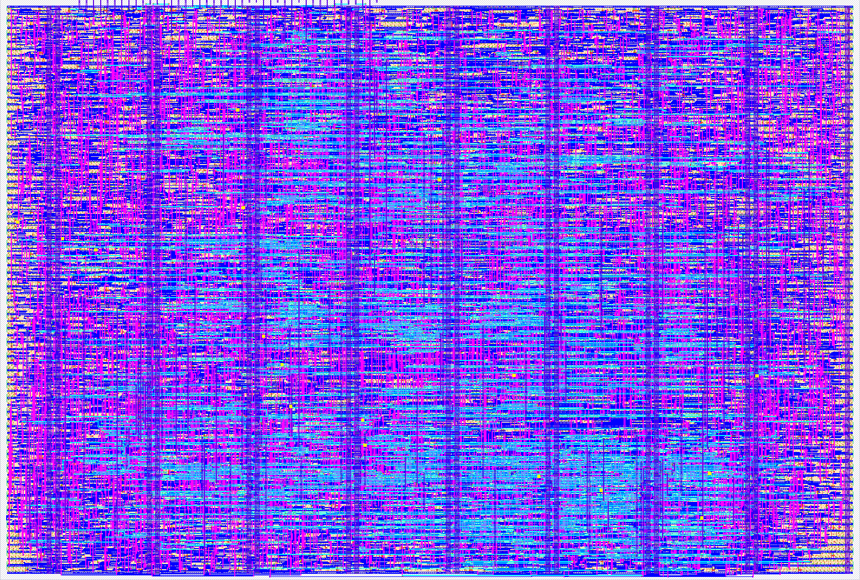
- Author: Moein Maleki
- Description: 16-bit five-stage ARM pipeline with forwarding and hazard detection. Program streamed from the QSPI Pmod flash, data in its PSRAM, a 16-bit value shown as four large digits on the TinyVGA Pmod, an internal demo ROM. First ARM core on Tiny Tapeout.
- GitHub repository
- Open in 3D viewer
- Open in Tiny Tapeout Explorer
- Open in VGA Playground
- Clock: 25000000 Hz
How it works
arm16 is a 16-bit five-stage ARM pipeline (fetch, decode, execute, memory, write-back) that executes a subset of the standard 32-bit ARM instruction encoding: MOV, MVN, ADD, ADC, SUB, SBC, AND, ORR, EOR, CMP, TST with immediate and shifted-register operands, LDR and STR of 16-bit words, B and BL, and the fifteen condition codes. Registers r0 to r14 are 16 bits wide; r15 is the program counter. The pipeline has forwarding from the memory and write-back stages and a load-use stall; a switch latched at reset turns the forwarding off so the two behaviours can be compared on silicon.
The program lives in the flash chip of the TinyTapeout QSPI Pmod and is streamed with the chip select held low (one command per branch, then eight memory clocks per instruction). Data lives in the Pmod's PSRAM. The memory clock is half the core clock. A 16-instruction ROM inside the chip holds a counting demo that runs with nothing on the memory socket.
Output goes to the TinyVGA Pmod: a hardware renderer paints the 16-bit value written to address 0xFF00 as four large hexadecimal digits (640x480 at 60 Hz from the 25 MHz clock). A second view shows the fetch address, and the background turns blue while the memory bus is active.
Address map: 0x0000 to 0x7FFF flash (fetch and load), 0x8000 to 0xFEFF PSRAM (load and store), 0xFF00 to 0xFFFF peripheral registers: 0xFF00 VGA_VAL, 0xFF02 SW (the input pins), 0xFF0C METER (instructions retired in the previous frame divided by 16), 0xFF10 VGA_FG and 0xFF12 VGA_BG (two bits per colour). The UART of the original specification was dropped for area; UART_EN still blanks the video.
How to test
With nothing on the memory socket: set BOOT_ROM (ui[6]) high, DISP_SEL (ui[1]) low, UART_EN (ui[2]) low, FWD_EN (ui[0]) high, fit the TinyVGA Pmod on the output socket, select the design at 25 MHz and release reset. The screen shows four digits counting. Set FWD_EN low and reset: the count runs about 2.23 times slower (the demo program is an eight-deep dependent chain). Set DISP_SEL high: the screen shows the program counter cycling through 0x0000 to 0x003C.
With the QSPI Pmod on the bidirectional socket: set the flash's quad-enable bit once (write enable 06h,
then 31h with S9 = 1, holding uio[4] and uio[5] high during those single-lane commands), program a flash
image built with test/arm16_asm.py (or arm-none-eabi-as -march=armv4 linked at address 0), set
BOOT_ROM low, set QSPI_DLY (ui[5:4]) to 2, and reset. The program runs from address 0. Try QSPI_DLY 1, 2
and 3 and record which work. Setting 2 passes the tested 0 to 40 ns round-trip range. At 15 ns it is the
only passing setting; two settings pass at 0 to 10 ns and at 20 to 40 ns.
Cut the demo board's seven-segment jumpers JP2 to JP9 before running with the TinyVGA Pmod, or the digit loads the resistor ladder.
External hardware
TinyVGA Pmod on the output socket (uo[0..7] = R1, G1, B1, VSYNC, R0, G0, B0, HSYNC) and a VGA monitor. QSPI flash and PSRAM Pmod on the bidirectional socket (uio[0] CS flash, uio[1] SD0, uio[2] SD1, uio[3] SCK, uio[4] SD2, uio[5] SD3, uio[6] CS PSRAM A, uio[7] CS PSRAM B held high). The demo ROM needs neither.
IO
| # | Input | Output | Bidirectional |
|---|---|---|---|
| 0 | FWD_EN | R1 | CS_FLASH |
| 1 | DISP_SEL | G1 | SD0 |
| 2 | UART_EN | B1 | SD1 |
| 3 | UART_RX | VSYNC | SCK |
| 4 | QSPI_DLY0 | R0 / UART_TX | SD2 |
| 5 | QSPI_DLY1 | G0 | SD3 |
| 6 | BOOT_ROM | B0 | CS_RAM_A |
| 7 | USER | HSYNC | CS_RAM_B |