512 Fatigue Monitor (PPG Pulse-Interval Variability)
512 : Fatigue Monitor (PPG Pulse-Interval Variability)
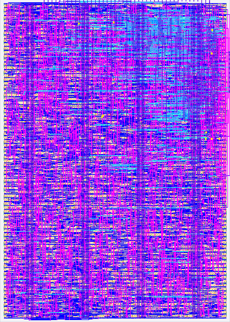
- Author: Ruhan Gupta
- Description: Reads IR PPG samples from a MAX30102 over I2C, detects pulse peaks, and raises an alert on a sustained drop in pulse-interval variability
- GitHub repository
- Open in 3D viewer
- Open in Tiny Tapeout Explorer
- Clock: 10000000 Hz
How it works
This is a complete fatigue-monitor pipeline: an I2C master initializes a MAX30102
breakout, reads IR pulse samples from its FIFO, removes the DC baseline, detects
each heartbeat, measures the time between beats, and compares recent variability
in that timing against a personal baseline learned during a short calibration
window. alert_out asserts after a sustained, persistent drop in variability
versus that baseline.
This is a full integration of the sensor-acquisition and signal-processing
modules built in earlier stages: tick_generator, i2c_byte_engine,
max30102_controller, dc_filter, peak_detector, interval_tracker,
interval_validator, variability_calculator, calibration_controller, and
alert_controller, all instantiated from tt_um_fatigue_monitor in
supporting_modules.v. LED current, ADC range, and filter constants
(FILTER_SHIFT, DC_FRAC_BITS, envelope/threshold shifts, refractory and
warm-up lengths) have been set from ESP32 sensor characterization and FPGA
bring-up on real hardware; they remain ordinary Verilog parameters and may
still be retuned if synthesis or further testing calls for it.
The peak detector also enforces a fixed absolute signal floor
(SIGNAL_FLOOR) before it will start tracking a rising edge, in addition to
its adaptive envelope/threshold. Without this floor, the adaptive threshold
collapses along with the envelope when no finger is on the sensor, and small
residual noise can cross that near-zero threshold at a very regular rate --
which looks exactly like the low-variability condition alert_out is meant
to catch, but on no real signal. The floor value was set from characterized
real-pulse AC amplitude.
How to test
Connect a MAX30102 breakout's SDA/SCL to uio[0]/uio[1] with external
pull-ups, share ground, and hold rst_n low then release it. uo[4]
(calibrating_init) stays high through sensor init and the ~2-3 minute
baseline-learning window; uo[5] pulses once per accepted IR sample if I2C
acquisition is alive; uo[3] (beat_debug) pulses once per detected
heartbeat. Once uo[2] (calibrated) goes high, uo[0] (alert_out) will
assert after a sustained drop in pulse-interval variability.
Bring-up order matters: first confirm uo[5] is pulsing (I2C/sensor path
alive) before worrying about alert_out, since a quiet uo[5] means the
fault is upstream in initialization or FIFO acquisition, not in the alert
logic.
uo[7] (rising_seen_debug) is a bring-up-only debug pin that mirrors the
peak detector's internal rising-edge-candidate flag, useful for confirming
the adaptive detector is seeing real signal shape with a logic analyzer. It
is not part of the functional interface and should be tied to 0 before a
final shuttle submission.
External hardware
Requires a MAX30102 breakout module (SDA/SCL to uio[0:1], shared ground,
pull-ups sized for the ASIC's I/O voltage) and, for a real alert output, an
external transistor/MOSFET driving a buzzer or vibration motor from
alert_out — the ASIC does not drive the actuator directly.
A logic analyzer or scope on uo[3:5] during bring-up is strongly
recommended, since those debug pins are the fastest way to tell whether a
failure is in sensor acquisition versus the alert logic further downstream.
IO
| # | Input | Output | Bidirectional |
|---|---|---|---|
| 0 | alert_out | I2C SDA | |
| 1 | sensor_fault | I2C SCL | |
| 2 | calibrated | ||
| 3 | beat_debug | ||
| 4 | calibrating_init | ||
| 5 | sample_valid | ||
| 6 | variability_valid | ||
| 7 | rising_seen_debug (bring-up only) |