650 GPS Daily Trigger
650 : GPS Daily Trigger
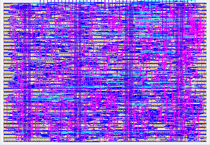
- Author: Costin-Emanuel Vasile
- Description: Configurable daily trigger generation synchronized to GPS UTC time and PPS
- GitHub repository
- Open in 3D viewer
- Open in Tiny Tapeout Explorer
- Clock: 50000000 Hz
How it works
This design generates one fixed-width trigger pulse per day at a configurable UTC hour, minute, and second. A preconfigured GPS receiver supplies 9600-baud NMEA data on UART_RX and a one-pulse-per-second reference on GPS_PPS.
The UART receiver extracts bytes from the GPS serial stream. The NMEA parser accepts $GPRMC sentences, validates their XOR checksum, verifies the A navigation-status field, and decodes the six UTC digits HHMMSS. Other NMEA sentence types are ignored.
An accepted RMC timestamp is associated with the next rising edge of GPS_PPS. The default configuration labels that PPS as one second after the RMC timestamp (ASSOCIATION_ADD_ONE=1). When the associated UTC time equals the configured daily target, TRIG_OUT is asserted for 50 ms. The relationship between the receiver's RMC timestamp and PPS edge should be confirmed with the intended GPS module before fabrication.
The target is configured through a small write-only parallel interface. CONFIG_FLD_1:0 selects the field and CONFIG_DATA_BIT_7:0 supplies its binary value:
CONFIG_FLD_1:0 |
Field | Valid values |
|---|---|---|
00 |
Hour | 0–23 |
01 |
Minute | 0–59 |
10 |
Second | 0–59 |
11 |
Invalid/reserved | — |
Set the field and data, keep them stable, and assert CONFIG_WE. The write strobe passes through a two-flip-flop synchronizer, so the field and data must remain stable for at least four clk cycles after CONFIG_WE rises. Deassert CONFIG_WE before writing the next field. The schedule becomes armed only after valid hour, minute, and second values have all been written. Starting a new configuration sequence disarms the previous target and clears any pending GPS timestamp.
The design expects a 50 MHz clk. All configured times are UTC rather than local time.
Pinout and status outputs
| Pin | Name | Function |
|---|---|---|
ui_in[0] |
UART_RX |
GPS NMEA serial input, 9600 baud, 8-N-1 |
ui_in[1] |
GPS_PPS |
GPS one-pulse-per-second input |
ui_in[2] |
ERR_CLR |
Rising edge clears sticky error outputs |
ui_in[3] |
CONFIG_WE |
Rising-edge configuration write strobe |
ui_in[5:4] |
CONFIG_FLD_1:0 |
Selects hour, minute, or second |
uio_in[7:0] |
CONFIG_DATA_BIT_7:0 |
Binary configuration value |
uo_out[0] |
TRIG_OUT |
Fixed 50 ms daily trigger pulse |
uo_out[1] |
GPS_SENTENCE_OK |
A valid RMC sentence was received recently |
uo_out[2] |
GPS_SENTENCE_NOK |
Sticky UART, format, or checksum error |
uo_out[3] |
GPS_FIX_INVALID |
Sticky RMC V/invalid-fix indication |
uo_out[4] |
CONFIG_ERR |
Sticky invalid field or value indication |
uo_out[5] |
PPS_OUT |
Synchronized PPS level for observation or an LED |
uo_out[6] |
UTC_PPS_LOCKED |
Most recent PPS was paired with an accepted RMC timestamp |
uo_out[7] |
TARGET_CONFIGURED |
All three target fields are valid and the schedule is armed |
GPS_SENTENCE_NOK, GPS_FIX_INVALID, and CONFIG_ERR are sticky. Pulse ERR_CLR high to clear them. Clearing errors does not erase the target configuration.
All eight uio pins are inputs in this design; uio_oe is always zero.
How to test
- Apply a 50 MHz clock and reset the design by driving
rst_nlow. - Connect the GPS transmitter to
UART_RX, GPS PPS toGPS_PPS, and connect the grounds. - Write target hour, minute, and second using
CONFIG_FLD,CONFIG_DATA, andCONFIG_WE. - Verify that
TARGET_CONFIGUREDbecomes high. - Wait for checksum-valid RMC messages and PPS.
GPS_SENTENCE_OKandUTC_PPS_LOCKEDshould become high, whilePPS_OUTfollows the synchronized PPS pulse. - At the configured UTC time, verify that
TRIG_OUTis high for approximately 50 ms. - Use
ERR_CLRto clear any sticky error indicators after diagnosing them.
The included cocotb testbench uses faster simulation-only parameters while testing the same protocol and trigger logic.
External hardware
A 3.3 V GPS receiver that outputs 9600-baud $GPRMC NMEA sentences and a PPS signal is required. Connect GPS TX to UART_RX, PPS to GPS_PPS, and GPS ground to the Tiny Tapeout board ground. Do not apply 5 V logic levels to the Tiny Tapeout I/O pins.
IO
| # | Input | Output | Bidirectional |
|---|---|---|---|
| 0 | UART_RX | TRIG_OUT | CONFIG_DATA_BIT_0 |
| 1 | GPS_PPS | GPS_SENTENCE_OK | CONFIG_DATA_BIT_1 |
| 2 | ERR_CLR | GPS_SENTENCE_NOK | CONFIG_DATA_BIT_2 |
| 3 | CONFIG_WE | GPS_FIX_INVALID | CONFIG_DATA_BIT_3 |
| 4 | CONFIG_FLD_0 | CONFIG_ERR | CONFIG_DATA_BIT_4 |
| 5 | CONFIG_FLD_1 | PPS_OUT | CONFIG_DATA_BIT_5 |
| 6 | UTC_PPS_LOCKED | CONFIG_DATA_BIT_6 | |
| 7 | TARGET_CONFIGURED | CONFIG_DATA_BIT_7 |