780 YEN
780 : YEN
- Author: JakubMiszczynski
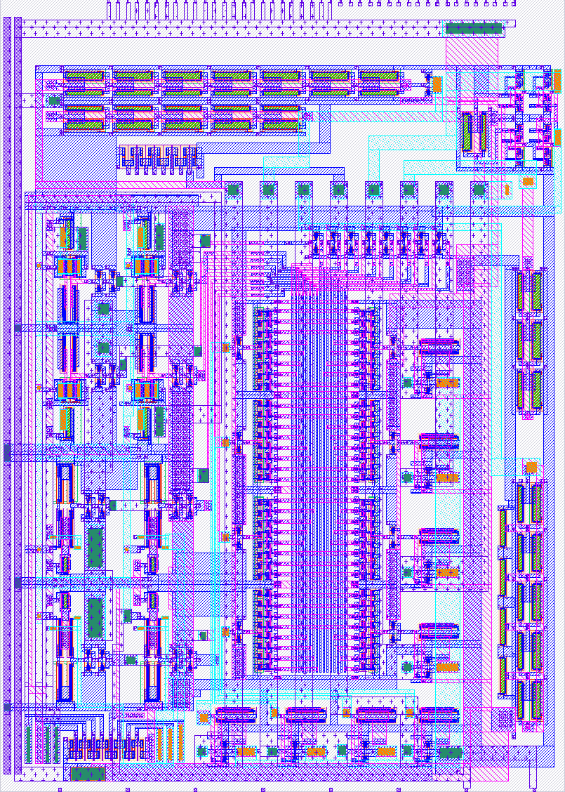
- Description: A TinyTapeout project featuring an analog-controlled 8-pin multiplexer and a set of ring oscillators and additional circuits for comprehensive testing of the design.
- GitHub repository
- Open in 3D viewer
- Clock: 0 Hz
How it works
The YEN project allows you to test up to 8 systems using only 2 analog pins. The system consists of two parts: Voltage Controlled MUX (MUX) and a block of test circuits. VCMUX works like any other MUX. In this case it has 8 analog inputs and 1 output. However, it is not controlled digitally but analogously. We apply a voltage from 0V to 1.8V to one of the pins of the system. The circuit has been designed in such a way that we have 8 thresholds every 200mV. Depending on the voltage provided, a different test circuit is connected to the second pin of the system. In this simple way, the number of systems that can be tested increases dramatically using only 2 pins.
Below are the thresholds and their arrangements: 0-200mV - nothing is connected to the output. We are investigating the interrogations and what kind of situation will arise in such a situation. 200mV-400mV - Ring oscillator consisting of 3 inverters. 400mV-600mV - Output of the ZQ T Flip Flop connected to a 5-ring inverter oscillator (it should be a frequency divider) 600mV-800mV - Ring oscillator consisting of 5 inverters. 800mV-1V - Output of Q T Flip Flop connected to 5 ring inverter oscillator (should be a frequency divider) 1V-1.2V - Ring oscillator consisting of 7 inverters. 1.2V-1.4V - Signal ring oscillator consisting of 7 inverters passed through an inverter with minimal dimensions. 1.4V-1.6V - Ring oscillator consisting of 5 inverters and capacitors. 1.6V-1.8V - Voltage from the resistor divider (about 0.2V)
The whole thing should not draw more than 1mA of current.
How to test
Test 0 - is the system alive? Apply 1.8V (supply voltage) to ua[1] and see if ua[0] is set to approximately 200mV.
Test 1 - Switching Thresholds. Apply DC voltage to UA[1] in the range 0-1.8V (preferably in 1mV steps). Record at what point the system switches. This should be visible by changing the oscillation frequency or setting a constant voltage at ua[0].
Test 2 - System performance. Now that you know each threshold, test each circuit. For example: set to ua[1] 300mV. On ua[0] you should see the ring output of the oscillator consisting of 3 inverters. Record frequency, apmlidute peak-peak and DC level. If so, can you also take a photo of the shape of the clock.
External hardware
- Laboratory power supply or other voltage source with the ability to set voltages in the range of 0-1.8V
- Multimeter
- Oscilloscope
IO
| # | Input | Output | Bidirectional |
|---|---|---|---|
| 0 | |||
| 1 | |||
| 2 | |||
| 3 | |||
| 4 | |||
| 5 | |||
| 6 | |||
| 7 |
Analog pins
ua | PCB Pin | Internal index | Description |
|---|---|---|---|
| 0 | B4 | 10 | VCMUXIN |
| 1 | B5 | 11 | VCMUXOUT |