806 SIMON64/128
806 : SIMON64/128
- Author: Philip Åkesson
- Description: SIMON64/128 crypto module with SPI interface
- GitHub repository
- Open in 3D viewer
- Clock: 50000000 Hz
Introduction
This is a Tiny Tapeout ASIC project implementing the SIMON64/128 lightweight block cipher with an SPI interface.
SIMON is a family of lightweight block ciphers published by the NSA in 2013, designed for efficient hardware implementation. Its sister family, SPECK, similarly targets software efficiency. This project implements SIMON64/128, which is a variant of SIMON using 64-bit blocks and 128-bit keys.
This project has not been hardened against side-channels or other cryptographic attacks.
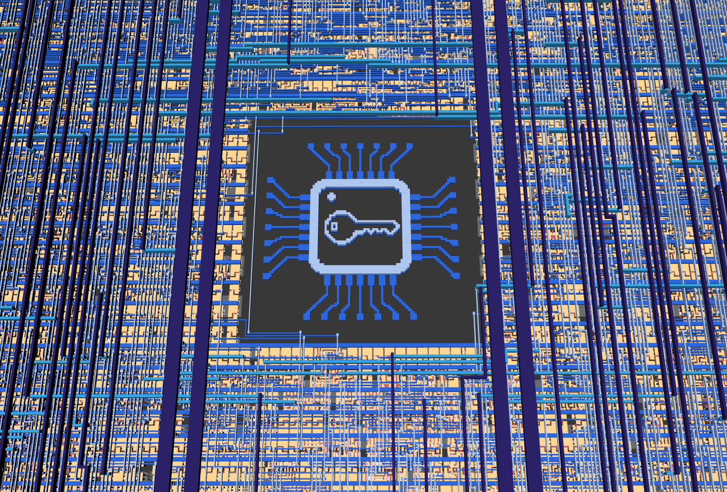
The ASIC implementation also includes an image illustrating a secure chip, on metal layers 1 and 2, shown in this 3D render:
Hardware Interface
The SIMON64/128 crypto module can be used through the RP2350 microcontroller on the demo board, or by connecting an external microcontroller or SPI adapter to the SPI pins.
| Pin | Signal |
|---|---|
uio[0] |
SPI CS_N |
uio[1] |
SPI SCK |
uio[2] |
SPI MOSI |
uio[3] |
SPI MISO |
SPI mode 0 is used, with clock polarity 0 and clock phase 0. Data is sampled (from MOSI) on rising clock edges, and shifted out (on MISO) on falling clock edges. Chip select is active low.
An SPI clock frequency of up to 6 MHz seems to work fine, with a 50 MHz system clock, when testing on an FPGA. Results may vary on the actual ASIC.
SPI Protocol
All SPI transfers are framed by CS_N.
The first byte in each SPI frame is always a command byte.
Data format:
- Multi-byte values are big-endian.
- Bits are shifted MSB-first.
- Key size is 16 bytes (128 bits).
- Block size is 8 bytes (64 bits).
Commands
| Command | Value | MOSI data (after command) | MISO data (after command) |
|---|---|---|---|
CMD_WRITE_KEY_128 |
0x10 |
16 key bytes | - |
CMD_WRITE_BLOCK_64 |
0x20 |
8 data bytes (plaintext or ciphertext) | - |
CMD_START_ENCRYPT |
0x30 |
- | - |
CMD_START_DECRYPT |
0x31 |
- | - |
CMD_READ_BLOCK_64 |
0x40 |
- | 8 data bytes (plaintext or ciphertext) |
CMD_READ_STATUS |
0x50 |
- | 1-byte status |
Status Byte (CMD_READ_STATUS)
Status bit layout:
- bits 7:3: unused, currently set to
0 - bit 2:
out_valid(1 when output block is ready) - bit 1:
core_busy(1 while encryption/decryption is running) - bit 0: always
1
Typical transaction sequence
- Send
CMD_WRITE_KEY_128with 16 key bytes. - Send
CMD_WRITE_BLOCK_64with 8 plaintext/ciphertext bytes. - Send
CMD_START_ENCRYPTorCMD_START_DECRYPT. - Poll
CMD_READ_STATUSuntil bit 2 (out_valid) becomes1. - Send
CMD_READ_BLOCK_64and clock out 8 bytes of result.
Notes:
- Writing a new block (
CMD_WRITE_BLOCK_64) clearsout_valid. - If
CMD_READ_BLOCK_64is issued whenout_valid=0, output data is not valid.
How It Works
This section covers parts of the SIMON cipher together with notes on the implementation in this project, but a lot of details are left out. For full details on the inner workings of SIMON, see the References section further down.
Overview
SIMON supports multiple variants and parameter sets based on word size (n), which determines the overall block size (2n). The key size is m*n bits, where m is 2, 3, or 4.
SIMON64/128 uses 32-bit words (n=32), 64-bit blocks (2n=64), and a 128-bit key (m=4) with 44 rounds.
SIMON is a balanced Feistel cipher, where (for SIMON64/128) the 64-bit block is split into two 32-bit halves, and each round updates one half using a nonlinear function of the other half plus a round key. The round function consists of bitwise operations and rotations (no S-boxes), which is helpful when implementing in limited area in hardware.
The project consists of three main Verilog modules: an SPI peripheral that handles communication with an external microcontroller, a SIMON64/128 cryptographic core that performs encryption and decryption, and a top-level wrapper that integrates them.
The full key and block are loaded as bytes over SPI and stored in a 128-bit key window register k_window and 64-bit block state (split into x_reg and y_reg). Round processing is then performed iteratively, bit-by-bit over multiple cycles, to reduce area.
Implementation Details
The round function is as follows:
R(x, y) = (y ^ F(x) ^ k_i, x)
where
F(x) = (ROL(x, 1) & ROL(x, 8)) ^ ROL(x, 2)
and k_i is the key-word for round i, ROL(x, n) is left-rotation (circular shift) of the word x by n bits.
The inverse round function is used for decryption:
R_inv(x, y) = (y, x ^ F(y) ^ k_i)
The code has a shared datapath for encryption/decryption, selected by the op_decrypt control bit and key-schedule direction/state.
Round keys are generated from the 128-bit key window. The key-schedule constant is c = 0xFFFF_FFFC (2^32-4 for n=32), and the schedule combines c, one z-sequence bit, and rotated/XOR-mixed key words to form the next key word.
For m=4, the key schedule is
k_{i+4} = C ^ z_i ^ k_i ^ ROR(k_{i+3}, 3) ^ k_{i+1} ^ ROR(ROR(k_{i+3}, 3) ^ k_{i+1}, 1)
where ROR(x, n) is right-rotation (circular shift) of the word x by n bits.
In the code, the key window is
k_window = {kw3, kw2, kw1, kw0}
and kw0 is always the active round-key word used one bit at a time as rk_bit = kw0[ctr_bit].
The key words are updated in place, so the core does not need to store all 44 round keys. Instead, it advances one key-schedule step for each round. Forwards (for encryption):
ks_word = C ^ z_bit ^ kw0 ^ ROR(kw3,3) ^ kw1 ^ ROR(ROR(kw3,3) ^ kw1,1)
k_window <= {ks_word, kw3, kw2, kw1}
After this, the next round uses the new kw0 (which is the previous kw1).
Backwards (for decryption):
ks_word = C ^ z_bit_inv ^ kw3 ^ ROR(kw2,3) ^ kw0 ^ ROR(ROR(kw2,3) ^ kw0,1)
k_window <= {kw2, kw1, kw0, ks_word}
This computes the previous round key and shifts it into kw0.
The 62-bit z-sequence (z3 for SIMON64/128) is generated using an LFSR with a 7-bit state (with P(x) = x^7 + x^4 + x + 1), which supports updating both backwards and forwards so that the key schedule can run in either direction.
Defining z_t = z_lfsr[0] at time t, the implementation is
z_{t+7} = z_{t+4} ^ z_{t+1} ^ z_t
Forward updates are
z_lfsr_fwd = {z_lfsr[4] ^ z_lfsr[1] ^ z_lfsr[0], z_lfsr[6:1]}
and backward updates
z_lfsr_bwd = {z_lfsr[5:0], z_lfsr[6] ^ z_lfsr[3] ^ z_lfsr[0]}
The forward and backward output bits are z_bit = z_lfsr[0] and z_bit_inv = z_lfsr[6] ^ z_lfsr[3] ^ z_lfsr[0] respectively.
Internally, each round is executed over 32 clock cycles (ctr_bit from 0 to 31). At each bit step, the core computes one new bit from the SIMON round function and the current round-key bit rk_bit = kw0[ctr_bit].
A warmup phase is used to (re-)align the key schedule direction and state between encryption and decryption operations.
Both encryption and decryption take 1410 clock cycles to complete without warmup, or 1453 clock cycles with warmup.
When an encryption or decryption operation has finished, the out_valid bit is set to 1.
The cryptographic implementation matches the behavior of the simonspeckciphers Python library, which is also verified as part of the automated tests.
How to Test
Automated tests using cocotb and pytest can be found under test/.
The easiest way to use this project is through MicroPython on the Tiny Tapeout demo board.
After the MicroPython examples below, this section also shows how to use an external FTDI breakout board to communicate through the bidirectional Pmod header from Python scripts running on a PC. Other external devices, such as microcontrollers or other SPI adapters, can be used in the same way.
Using with MicroPython on the TT Demo Board
The Tiny Tapeout demo board includes an RP2350 running MicroPython, which can be used to test this project.
The full code below can also be found in micropython/micropython_example.py.
First, set up some utility functions:
CMD_WRITE_KEY_128 = 0x10
CMD_WRITE_BLOCK_64 = 0x20
CMD_START_ENCRYPT = 0x30
CMD_START_DECRYPT = 0x31
CMD_READ_BLOCK_64 = 0x40
CMD_READ_STATUS = 0x50

def spi_write_cmd_and_payload(spi, cmd, payload=None):
    spi_cs(0)
    spi.write(bytes([cmd]))
    if payload:
        spi.write(payload)
    spi_cs(1)

def spi_read_status(spi):
    spi_cs(0)
    spi.write(bytes([CMD_READ_STATUS]))
    status = spi.read(1)
    spi_cs(1)
    return status

def spi_read_block64(spi):
    spi_cs(0)
    spi.write(bytes([CMD_READ_BLOCK_64]))
    data = spi.read(8)
    spi_cs(1)
    return data

def wait_spi_done(spi, max_polls=1000):
    for _ in range(max_polls):
        status = spi_read_status(spi)[0]
        if status & 0x1 == 0: # The low bit should always be 1
            return False
        if ((status >> 2) & 0x1):
            return True
    return False

def encrypt(spi, plaintext, key):
    spi_write_cmd_and_payload(spi, CMD_WRITE_KEY_128, key)
    spi_write_cmd_and_payload(spi, CMD_WRITE_BLOCK_64, plaintext)
    spi_write_cmd_and_payload(spi, CMD_START_ENCRYPT)
    status = wait_spi_done(spi)
    if not status:
        return b''
    return spi_read_block64(spi)

def decrypt(spi, ciphertext, key):
    spi_write_cmd_and_payload(spi, CMD_WRITE_KEY_128, key)
    spi_write_cmd_and_payload(spi, CMD_WRITE_BLOCK_64, ciphertext)
    spi_write_cmd_and_payload(spi, CMD_START_DECRYPT)
    status = wait_spi_done(spi)
    if not status:
        return b''
    return spi_read_block64(spi)
Next, initialize SPI:
spi_cs = tt.pins.pin_uio0
spi_clk = tt.pins.pin_uio1
spi_mosi = tt.pins.pin_uio2
spi_miso = tt.pins.pin_uio3

spi_miso.init(spi_miso.IN, spi_miso.PULL_DOWN)
spi_cs.init(spi_cs.OUT)
spi_clk.init(spi_clk.OUT)
spi_mosi.init(spi_mosi.OUT)

spi = machine.SPI(1, baudrate=6000000, polarity=0, phase=0, bits=8, firstbit=machine.SPI.MSB, sck=spi_clk, mosi=spi_mosi, miso=spi_miso)

spi_cs(1) # Initial value for CS
Then test encryption and decryption:
key = bytes.fromhex("1b1a1918131211100b0a090803020100")
plain = bytes.fromhex("656b696c20646e75")
expected_ct = bytes.fromhex("44c8fc20b9dfa07a")

ct = encrypt(spi, plain, key)
print("Ciphertext:", ct.hex())
assert ct == expected_ct, "Encryption failed"

pt = decrypt(spi, ct, key)
print("Decrypted plaintext:", pt.hex())
assert pt == plain, "Decryption failed"
External SPI Using an FTDI Breakout Board
Before using SPI externally through the bidirectional Pmod header, ensure that the corresponding pins on the RP2350 on the demo board are set as inputs (without pull-downs or pull-ups).
Example code using the PyFtdi Python library can be found in python/pyftdi_example.py.
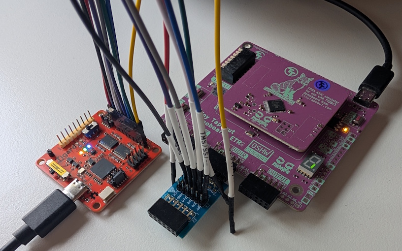
All examples have been tested with the Tigard FT2232H breakout board:
Running the script without parameters prints usage information:
$ uv run pyftdi_example.py
usage: pyftdi_example.py [-h] [--list-devices] [--device DEVICE] [--encrypt | --decrypt] [--key KEY] [--data DATA]
pyftdi_example.py: error: Specify one operation: --encrypt or --decrypt
Use --list-devices to find your device configuration:
$ uv run pyftdi_example.py --list-devices
Available interfaces:
  ftdi://ftdi:2232:TG11163f/1  (Tigard V1.1)
  ftdi://ftdi:2232:TG11163f/2  (Tigard V1.1)
The example code uses the FT2232H's second interface by default, but you can configure and use any compatible FTDI device by setting --device DEVICE.
If only one FTDI device is connected, you can also use just ftdi:///1 for the first interface, ftdi:///2 for the second and so on.
Set the key with --key and data (plaintext or ciphertext) with --data, and then use --encrypt or --decrypt to encrypt or decrypt data, respectively:
$ uv run pyftdi_example.py --encrypt --key 1b1a1918131211100b0a090803020100 --data 656b696c20646e75
Ciphertext: 44c8fc20b9dfa07a

$ uv run pyftdi_example.py --decrypt --key 1b1a1918131211100b0a090803020100 --data 44c8fc20b9dfa07a
Plaintext: 656b696c20646e75
Use a specific FTDI device like this:
$ uv run pyftdi_example.py --decrypt --device ftdi://ftdi:2232:TG11163f/2 --key 1b1a1918131211100b0a090803020100 --data 44c8fc20b9dfa07a
Plaintext: 656b696c20646e75
References
A bit-serial implementation of SIMON128 has previously been taped out on Tiny Tapeout 8 and IHP 25a, by Secure-Embedded-Systems. That implementation has a fixed hard-coded (all zero) key and uses a custom 3-bit input and 2-bit output interface, but it also fits in only one Tiny Tapeout tile (instead of two, like this project).
The simonspeckciphers Python library was used as a reference, and is also included in the cocotb tests for this project.
The following papers were also used as references:
IO
| # | Input | Output | Bidirectional |
|---|---|---|---|
| 0 | SPI CS_N | ||
| 1 | Busy | SPI SCK | |
| 2 | Out valid | SPI MOSI | |
| 3 | SPI MISO | ||
| 4 | |||
| 5 | |||
| 6 | |||
| 7 |