143 FFD16 cpu 16-bit
143 : FFD16 cpu 16-bit

- Author: Bahri Berkant İçöz
- Description: 16-bit spi cpu
- GitHub repository
- Open in 3D viewer
- Clock: 25000000 Hz
Remedy CPU / TinyCPU Datasheet
How to test
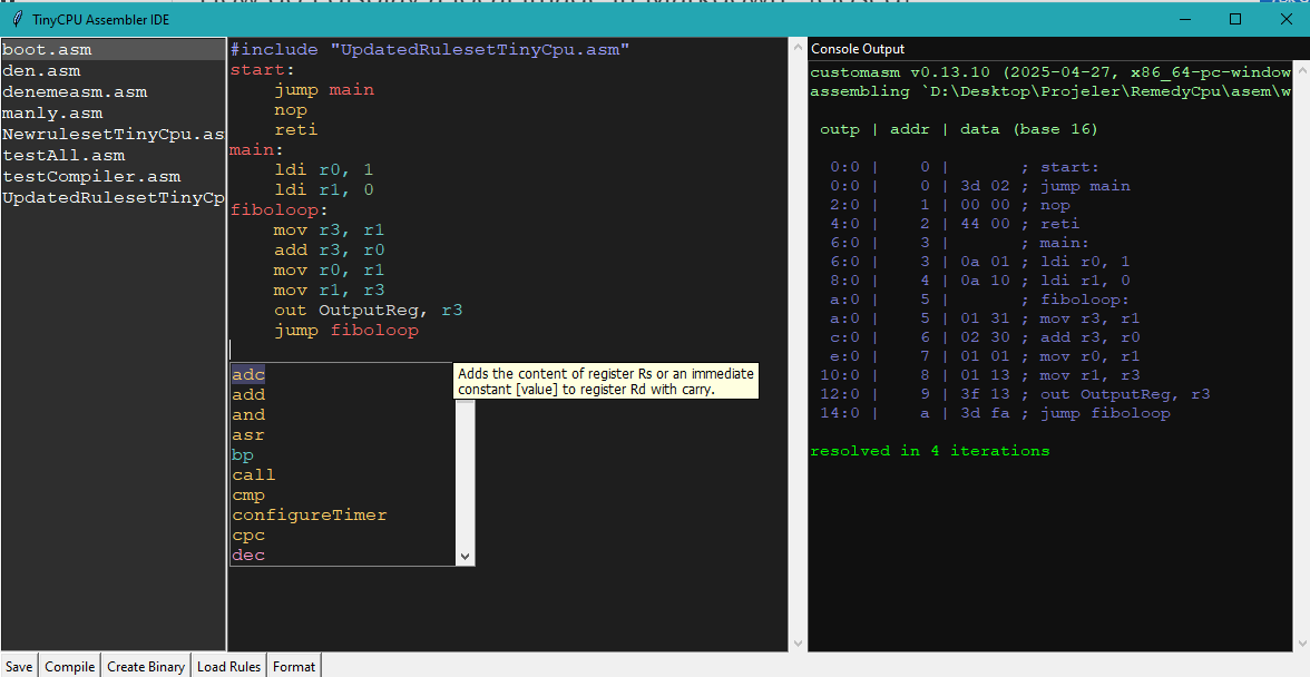
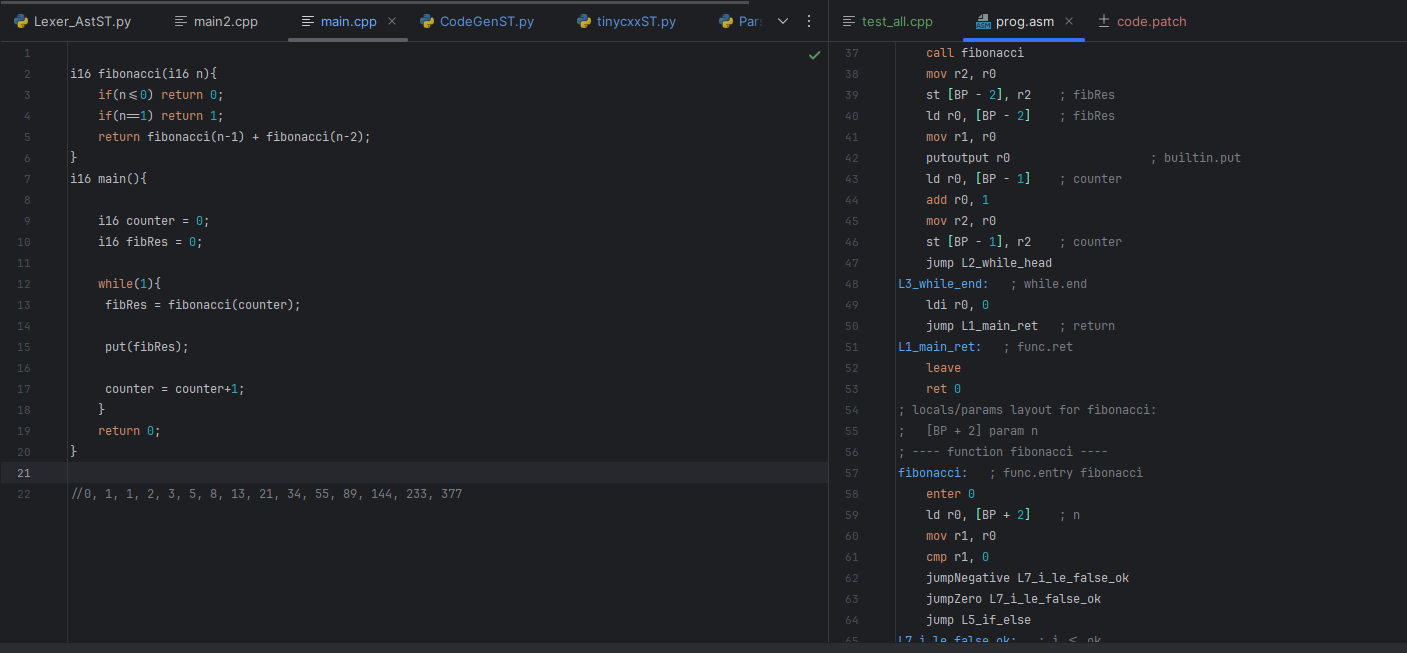
Use the custom IDE/toolchain to assemble TinyCPU assembly, or the work-in-progress cpp-ish compiler, then upload the generated program image to the external flash. I am also working on a vscode extension to integrate these steps into a more user-friendly workflow. with code upload, flash programming, and serial debugging features hopefully.
Here is the Repo link : https://github.com/leonidas213/Remedy-Compiler
Assembler
Work in progress compiler
External hardware
The CPU uses external serial memory instead of internal program/data memory.
| Device | Mode used by current hardware | Purpose |
|---|---|---|
| SPI/QSPI Flash | QSPI continuous-read mode | Program fetch and ldf flash reads |
| SPI RAM / PSRAM | Plain SPI mode | Data load/store |
The CPU is a 16-bit design and only reads/writes memory in 16-bit half-words. CPU memory addresses are word addresses. Externally, the memory interface appends one zero bit to form byte addresses, so CPU address 0x0001 maps to external byte address 0x000002.
Usable external address range:
CPU word address: 0x0000-0xFFFF
External byte address used: 0x00000-0x1FFFF
Effective byte range: 128 KiB per memory device
Example: if flash byte memory starts with 0x3D F1 25 48, the CPU can read 0x3DF1 at word address 0x0000 and 0x2548 at word address 0x0001. It cannot directly read the unaligned half-word 0xF125.
Pin usage
| Pin group | Use |
|---|---|
ui_in[5:0] |
General input pins |
ui_in[6] |
Debug serial data input |
ui_in[7] |
Debug serial clock input |
uo_out[5:0] |
General output pins from OutputReg[5:0] |
uo_out[6] |
General output OutputReg[6], or I2C SCL when I2C is active |
uo_out[7] |
General output OutputReg[7], or debugger data output when debugger drives it |
uio[0] |
Flash CS |
uio[1] |
Flash/RAM IO0 / MOSI |
uio[2] |
Flash/RAM IO1 / MISO |
uio[3] |
Shared serial clock |
uio[4] |
Flash IO2 |
uio[5] |
Flash IO3 |
uio[6] |
RAM CS |
uio[7] |
I2C SDA |
Memory interface
Startup flash initialization
At reset the memory interface initializes the flash before the CPU can fetch instructions. The current startup sequence is:
0x66              ; flash reset enable
0x99              ; flash reset
0x06              ; write enable
0x31 0x02         ; set status/config register 2, enable quad mode
0xEB              ; enter QSPI fast-read/continuous-read path
0x00 0x00 0x00 0xA0 0x00 0x00
                  ; address 0, mode bits A0, dummy clocks
RAM reset/init was removed to save area. RAM CS stays high during flash initialization.
Runtime flash read
Flash is treated as read-only by this memory interface. Runtime flash access uses QSPI continuous read:
CS low
24-bit byte address = {7'b0, cpu_addr[15:0], 1'b0}
2 QSPI mode nibbles: A, 0
4 QSPI dummy clocks
4 QSPI data clocks = 16-bit word
CS high
The external SPI/QSPI clock toggles every system clock, so one external serial clock period is two system clock cycles.
Runtime RAM read/write
RAM uses normal SPI:
Read command  = 0x03
Write command = 0x02
24-bit byte address = {1'b0, 6'b0, cpu_addr[15:0], 1'b0}
16-bit data word
Flash writes are intentionally blocked in the current memory wrapper.
CPU specs
Overview
- 16-bit CPU datapath
- 16 general purpose 16-bit registers
r13/BP,r14/SP, andr15/RAare conventionally used as branch pointer, stack pointer, and return address, but they are still can be used as normal registers- 16-bit instruction words
- Immediate words have MSB = 1 and load the immediate register instead of executing as a normal opcode
- External flash and RAM are accessed only as 16-bit half-words
- ALU flags: Negative, Zero, Carry
- Fixed interrupt vector:
0x0002 - Debugger supports halt/run/step, one dynamic breakpoint, static
brk, and jump/load-PC
Immediate format
Any fetched word with bit 15 set is treated as an immediate word. It updates the immediate register and does not execute as a normal instruction. The following real instruction can then consume that immediate value.
Example concept:
; Assembly:
jump 0xF123

; Encoded as two 16-bit words:
0xF123     ; immediate word
0x3C01     ; absolute jump instruction using the immediate register/sign bit field
This is why the debugger can also inject multi-word commands by feeding the same 16-bit words the flash would have returned.
Timers
There are two timers:
| Timer | Counter width | Target width | Read address |
|---|---|---|---|
| Timer 1 | 16-bit | 16-bit | timer1ReadAdr = 5 |
| Timer 2 | 9-bit | 9-bit | timer2ReadAdr = 9 |
Timer 2 is called the tiny timer in the RTL, but it is currently 9-bit, not 8-bit.
Both timers use the same 8-bit config layout:
| Bit(s) | Name | Meaning |
|---|---|---|
[0] |
enable | Enables the timer |
[4:1] |
prescaler | Prescaler select |
[5] |
auto reload | When target matches, reset count to zero instead of staying at target |
[6] |
IRQ enable | Timer asserts interrupt when target matches |
Prescaler encoding:
| Value | Divide |
|---|---|
| 0 | /1 |
| 1 | /2 |
| 2 | /4 |
| 3 | /8 |
| 4 | /16 |
| 5 | /32 |
| 6 | /64 |
| 7 | /128 |
| 8 | /256 |
| 9 | /512 |
| 10 | /1024 |
| 11 | /2048 |
| 12-15 | reserved/currently behaves like /1 |
Examples:
| Source | Prescaler | Timer tick |
|---|---|---|
| System clock | /2048 |
81.92 us |
Max overflow times with /2048:
| Timer | System clock source |
|---|---|
| 16-bit timer | about 5.37 s |
| 9-bit timer | about 41.94 ms |
Notes:
- A target value of zero disables match detection because the RTL uses
target != 0astarget_valid. - During interrupt lock (
InterLock), the timer count does not advance. The prescaler can still advance when the timer is enabled. - Writing to the timer reset address with bit 0 set clears count, clears prescaler, and clears timer config.
- Writing
timerSyncStartupdates bit 0, the enable bit, of both timer configs at the same time.
Interrupts
The interrupt system uses one fixed interrupt vector and software dispatch:
Interrupt vector = 0x0002
Return instruction = reti
Interrupt sources:
| Bit | Source |
|---|---|
| 0 | Timer 1 |
| 1 | Timer 2 |
| 2 | I2C |
There is no separate per-input-pin interrupt source in the current top-level wiring.
Interrupt registers:
| Address | Name | Write behavior | Read behavior |
|---|---|---|---|
| 13 | CpuinterruptEnable |
bit 0 = global interrupt enable | bit 0 = global enable, bit 1 = IRQ lock, bit 2 = active interrupt request |
| 14 | InputInterruptEnable |
bits [2:0] = IRQ source enable mask |
current IRQ enable mask |
| 15 | InterruptRegister |
write 1s to clear pending bits | current pending bits |
Important behavior:
- IRQ requests are latched into pending bits.
InterruptRegisteris write-one-to-clear.- Interrupts are blocked while
immis active, so an interrupt should not break an immediate word plus the following immediate-consuming instruction. - Once an interrupt is taken, the controller locks until
retiis executed. - If another source becomes pending while locked, it remains pending and can trigger after
retiif still enabled.
A typical ISR should read InterruptRegister, handle each set bit, clear the handled bits by writing 1s back to InterruptRegister, then execute reti.
I2C master
The I2C block is now a small fixed-speed master. It does not use the old programmable 16-bit prescaler anymore.
Approximate SCL rate:
SCL ≈ clk / (3 * (I2C_DIV + 1))
I2C_DIV = 20
At 25 MHz: SCL ≈ 397 kHz
I2C register map:
| CPU address | Lower I2C reg | Name | Description |
|---|---|---|---|
| 16 | 0 | I2cCtrl |
bit 0 = enable, bit 1 = IRQ enable |
| 17 | 1 | I2cStatus |
bit 0 busy, bit 1 bus active, bit 2 done, bit 3 ack error, bit 4 rx valid, bit 5 interrupt pending/done |
| 18 | 2 | I2cDivider / legacy I2cPrescaler |
read-only divider value, currently 20 |
| 19 | 3 | I2cDataReg |
write TX byte / read RX byte |
| 20 | 4 | I2cCommand |
command bits |
I2cStatus sticky bits are cleared by writing 1s:
| Status bit | Clear behavior |
|---|---|
| 2 | write 1 to clear done |
| 3 | write 1 to clear ack_error |
| 4 | write 1 to clear rx_valid |
Command register bits:
| Bit | Command |
|---|---|
| 0 | START |
| 1 | STOP |
| 2 | WRITE byte |
| 3 | READ byte |
| 4 | NACK after read |
You can combine bits, for example START+WRITE for address phase, READ+NACK+STOP for the final byte of a read transaction.
Debugger
The debug serial frontend receives 32-bit frames using the debug clock and debug data input:
8'hA5 sync + 4-bit command + 4-bit register address + 16-bit data
Commands:
| Command | Meaning |
|---|---|
| 0 | Ping |
| 1 | Read debug register |
| 2 | Write debug register |
Responses are 16-bit:
| Response | Meaning |
|---|---|
0xDB12 |
Ping response |
0xACCE |
Write accepted |
| read data | Read command response |
0xEEEE |
Invalid/error response |
Debug registers:
| Reg | Name | Description |
|---|---|---|
| 0 | ID | reads 0xDB11 |
| 1 | STATUS | bit 0 halt request, bit 1 jump pending, bit 3 halted, bit 4 debug enable, bit 5 static break enable, bit 6 breakpoint enable, bit 7 resume mask |
| 2 | CONTROL | bit 0 debug enable, bit 1 halt request, bit 2 run pulse, bit 3 step pulse, bit 5 static break enable, bit 6 jump/load-PC request |
| 3 | FLAGS | bit 0 Negative, bit 1 Zero, bit 2 Carry |
| 4 | PC | current program counter |
| 5 | IR | current instruction register |
| 6 | BP0 | dynamic breakpoint address |
| 7 | BPCTRL | bit 0 enables BP0 |
| 8 | JUMP_ADDR | address used by CONTROL bit 6 |
Only one dynamic breakpoint is currently implemented. The static breakpoint instruction is opcode 0x49 / brk; it only halts when static break is enabled.
Register map
InputReg               = 0    ; 16-bit read, lower 8 bits contain input pins/debug pins
OutputReg              = 1    ; 8-bit output register

timer1Config           = 2    ; 8-bit timer config
timer1Target           = 3    ; 16-bit target
timer1Reset            = 4    ; write bit 0 = reset timer1
timer1ReadAdr          = 5    ; read 16-bit timer1 count

timer2Config           = 6    ; 8-bit timer config
timer2Target           = 7    ; 9-bit target
timer2Reset            = 8    ; write bit 0 = reset timer2
timer2ReadAdr          = 9    ; read 9-bit timer2 count, zero-extended

timerSyncStart         = 10   ; write bit 0 to update enable bit of both timers

RandomSeedAddr         = 11   ; write 8-bit RNG seed
RandomReg              = 12   ; read generated random value

CpuinterruptEnable     = 13   ; global interrupt control/status
InputInterruptEnable   = 14   ; IRQ source enable mask, legacy name
InterruptRegister      = 15   ; IRQ pending register, write-one-to-clear

I2cCtrl                = 16
I2cStatus              = 17
I2cDivider             = 18   ; fixed divider readback, legacy name I2cPrescaler
I2cDataReg             = 19
I2cCommand             = 20
Programming examples
Basic addition and store
ldi r1, 0x12
ldi r2, 0x20
add r1, r2
st 0x1000, r1
putoutput r1
Timer 1, system-clock source, /2048, IRQ enabled, auto reload enabled
Config value:
irq=1, reload=1, prescaler=11, enable=1
config = (1<<6) | (1<<5) | (11<<1) | 1 = 0x77
ldi r1, 0x77
out timer1Config, r1
ldi r1, 1000
out timer1Target, r1
Timer 2, /2048, IRQ enabled, auto reload enabled
Config value:
irq=1, reload=1, prescaler=11, enable=1
config = (1<<6) | (1<<5) | (11<<1) | 1 = 0xF7
ldi r1, 0xF7
out timer2Config, r1
ldi r1, 511
out timer2Target, r1
Interrupt handler skeleton
jump main
nop
interrupt_handler: ;at memory address 0x0002
    in r0, InterruptRegister

    ; timer1 pending?
    mov r1, r0
    and r1, 1
    jumpZero check_timer2
    ; handle timer1 here
    ldi r1, 1
    out InterruptRegister, r1

check_timer2:
    mov r1, r0
    and r1, 2
    jumpZero check_i2c
    ; handle timer2 here
    ldi r1, 2
    out InterruptRegister, r1

check_i2c:
    mov r1, r0
    and r1, 4
    jumpZero irq_done
    ; handle i2c here
    ldi r1, 4
    out InterruptRegister, r1

irq_done:
    reti

main:
    ; main program here
    jump main
Opcode Table
| Opcode | Instruction | Description |
|---|---|---|
0x00 |
nop |
Does nothing. |
0x01 |
mov rd, rs |
Move the content of Rs to register Rd |
0x02 |
add rd, rs |
Adds the content of register Rs to register Rd without carry. |
0x03 |
adc rd, rs |
Adds the content of register Rs to register Rd with carry. |
0x04 |
sub rd, rs |
Subtracts the content of register Rs from register Rd without carry. |
0x05 |
sbc rd, rs |
Subtracts the content of register Rs from register Rd with carry. |
0x06 |
and rd, rs |
Performs a bitwise AND between Rd and Rs, and stores the result in Rd. |
0x07 |
or rd, rs |
Performs a bitwise OR between Rd and Rs, and stores the result in Rd. |
0x08 |
xor rd, rs |
Performs a bitwise XOR between Rd and Rs, and stores the result in Rd. |
0x09 |
ldi rd, i16 |
Loads Register Rd with the constant value [value]. |
0x0A |
ldi rd, u4 |
Loads Register Rd with the constant value [value]. |
0x0B |
add rd, i16 |
Adds an immediate constant [value] to register Rd without carry. |
0x0C |
add rd, u4 |
Adds an immediate constant [value] to register Rd without carry. |
0x0D |
adc rd, i16 |
Adds an immediate constant [value] to register Rd with carry. |
0x0E |
adc rd, u4 |
Adds an immediate constant [value] to register Rd with carry. |
0x0F |
sub rd, i16 |
Subtracts an immediate constant [value] from register Rd without carry. |
0x10 |
sub rd, u4 |
Subtracts an immediate constant [value] from register Rd without carry. |
0x11 |
sbc rd, i16 |
Subtracts an immediate constant [value] from register Rd with carry. |
0x12 |
sbc rd, u4 |
Subtracts an immediate constant [value] from register Rd with carry. |
0x13 |
neg rd |
Stores the two's complement of Rd in register Rd. |
0x14 |
and rd, i16 |
Performs a bitwise AND between Rd and an immediate constant [value], and stores the result in Rd. |
0x15 |
and rd, u4 |
Performs a bitwise AND between Rd and an immediate constant [value], and stores the result in Rd. |
0x16 |
or rd, i16 |
Performs a bitwise OR between Rd and an immediate constant [value], and stores the result in Rd. |
0x17 |
or rd, u4 |
Performs a bitwise OR between Rd and an immediate constant [value], and stores the result in Rd. |
0x18 |
xor rd, i16 |
Performs a bitwise XOR between Rd and an immediate constant [value], and stores the result in Rd. |
0x19 |
xor rd, u4 |
Performs a bitwise XOR between Rd and an immediate constant [value], and stores the result in Rd. |
0x1A |
not rd |
Stores not Rd in register Rd. |
0x1B |
reserved |
|
0x1C |
reserved |
|
0x1D |
reserved |
|
0x1E |
cmp rd, rs |
Compares Rd, and Rs (subtracts Rs from Rd without storing the result) Without using carry flag. Flags are updated accordingly. |
0x1F |
cpc rd, rs |
Compares Rd, and Rs (subtracts Rs from Rd without storing the result) With carry flag. Flags are updated accordingly. |
0x20 |
cmp rd, i16 |
Compares Rd, and an immediate constant [value] (subtracts Rs from Rd without storing the result) Without using carry flag. Flags are updated accordingly. |
0x21 |
cmp rd, u4 |
Compares Rd, and an immediate constant [value] (subtracts Rs from Rd without storing the result) Without using carry flag. Flags are updated accordingly. |
0x22 |
cpc rd, i16 |
Compares Rd, and an immediate constant [value] (subtracts Rs from Rd without storing the result) With carry flag. Flags are updated accordingly. |
0x23 |
cpc rd, u4 |
Compares Rd, and an immediate constant [value] (subtracts Rs from Rd without storing the result) With carry flag. Flags are updated accordingly. |
0x24 |
lsl rd |
Shifts register Rd by one bit to the left. A zero bit is filled in and the highest bit is moved to the carry bit. |
0x25 |
lsr rd |
Shifts register Rd by one bit to the right. A zero bit is filled in and the lowest bit is moved to the carry bit. |
0x26 |
rol rd |
Shifts register Rd by one bit to the left. The carry bit is filled in and the highest bit is moved to the carry bit. |
0x27 |
ror rd |
Shifts register Rd by one bit to the right. The carry bit is filled in and the lowest bit is moved to the carry bit. |
0x28 |
asr rd |
Shifts register Rd by one bit to the right. The MSB remains unchanged and the lowest bit is moved to the carry bit. |
0x29 |
swap rd |
Swaps the high and low byte in register Rd. |
0x2A |
swapn rd |
Swaps the high and low nibbles of both bytes in register Rd. |
0x2B |
st [rd], rs |
Stores the content of register Rs to the memory at the address [Rd] from Ram. |
0x2C |
ld rd, [rs] |
Loads the value at memory address [Rs] to register Rd from Ram. |
0x2D |
st i16, rd |
Stores the content of register Rs to memory at the location given by [const] from Ram. |
0x2E |
st u4, rd |
Stores the content of register Rs to memory at the location given by [const] from Ram. |
0x2F |
ld rd, i16 |
Loads the memory value at the location given by [const] to register Rd from Ram. |
0x30 |
ld rd, u4 |
Loads the memory value at the location given by [const] to register Rd from Ram. |
0x31 |
st [rd +- value], rs |
Stores the content of register Rs to the memory at the address (Rd+[const]) from Ram. |
0x32 |
ld rd, [rs +- value] |
Loads the value at memory address (Rs+[const]) to register Rd from Ram. |
0x33 |
Reserved |
|
0x34 |
jumpCarry i8 |
Jump if Carry flag is set. (Relative, max jump +-128). |
0x35 |
jumpZero i8 |
Jump if Zero flag is set. (Relative, max jump +-128). |
0x36 |
jumpNegative i8 |
Jump if Negative flag is set. (Relative, max jump +-128). |
0x37 |
jumpNotCarry i8 |
Jump if Carry flag is not set. Relative jump. |
0x38 |
jumpNotZero i8 |
Jump if Zero flag is not set. Relative jump. |
0x39 |
jumpNotNegative i8 |
Jump if Negative flag is not set. Relative jump. |
0x3A |
rcall rd, i16 |
store current value to the Rd register and jump to immediate value. |
0x3B |
rret rs |
Return/jump to the address stored in register Rs. |
0x3C |
jump i16 |
absolute Jump to memory address. |
0x3D |
jump i8 |
Relative jump using signed offset. Assembler chooses this when possible. |
0x3E |
out i16, rs |
writes Rd register value to the immediate address. |
0x3F |
out u4, rs |
writes Rd register value to the immediate address. |
0x40 |
outr [rd], rs |
writes Rd value to the adress in the Rs register. |
0x41 |
in rd, i16 |
Reads the value at immediate address into Rd. |
0x42 |
in rd, u4 |
Reads the value at immediate address into Rd. |
0x43 |
inr rd, [rs] |
Reads the value at Rs value address into Rd. |
0x44 |
reti |
Only used in interrupt function. it will return to the address when the interrupt happened. |
0x45 |
ldf rd, [rs] |
Reads the value at Rs value address into Rd from flash memory. |
0x46 |
ldf rd, i16 |
Reads the immediate address into Rd from flash memory. |
0x47 |
ldf rd, u4 |
Reads the immediate address into Rd from flash memory. |
0x48 |
ldf rd, [rs +- value] |
Loads the value at memory address (Rs+-[const]) to register Rd from flash memory. |
0x49 |
brk |
Static breakpoint instruction. Only halts when debugger static break is enabled. |
IO
| # | Input | Output | Bidirectional |
|---|---|---|---|
| 0 | cpu input pin [0] | cpu output pin [0] | spi_flash_cs |
| 1 | cpu input pin [1] | cpu output pin [1] | spi_miso/Qdio[0] |
| 2 | cpu input pin [2] | cpu output pin [2] | spi_mosi/Qdio[1] |
| 3 | cpu input pin [3] | cpu output pin [3] | spi_sclk |
| 4 | cpu input pin [4] | cpu output pin [4] | Qdio[2] |
| 5 | cpu input pin [5] | cpu output pin [5] | Qdio[3] |
| 6 | cpu input pin [6] / Debug clock | cpu output pin [6] / I2c_scl | spi_ram_cs |
| 7 | cpu input pin [7] / Debug Data In | cpu output pin [7] / Debug Data Out | I2c_sda |