41 8-bit CPU
41 : 8-bit CPU

- Author: Matthew Papadimitrou, Wentan Su
- Description: An 8-bit CPU that performs instructions such as arithmetic and load instructions, and outputs the result of each instruction.
- GitHub repository
- Open in 3D viewer
- Clock: 25000000 Hz
How it works
Our goal for this project is to implement 8-bit CPU using the TinyTapout. Below, you will find the proposal diagram that we plan to work on over the term, based off time and complexity restraints we will focus on adding more features to our cpu as needed
Architecture
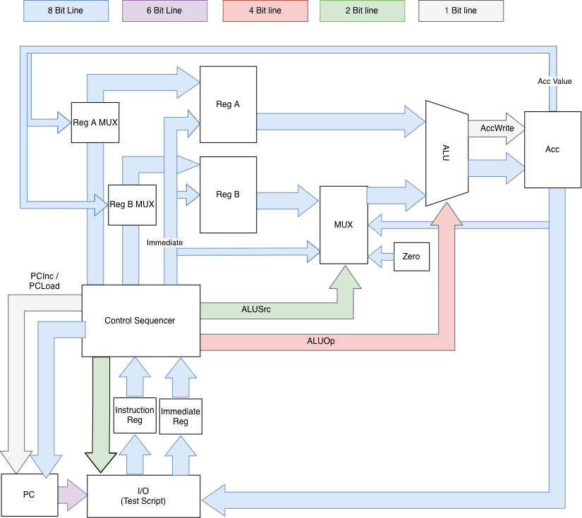
As seen in the diagram he CPU's architecture is coordinated by seperate unit blocks:
Control Sequencer:
- This will be the brains of the CPU. A state machine that takes in instructions from the I/O. A lookup table is used to store control signals for all valid instructions. The LUT interprets an instruction and returns what units of the CPU need to be activated to get the requested output
Arithmetic Logic Unit (ALU):
- This unit takes in an input from the registers and performs mathematical operations based off the request from Control Sequencer (Add, Sub, etc). It then writes the output to the accumulator
Registers:
- Index (A and B): Two 8-bit registers used for tempory storage
- Accumulator (Acc): An 8-bit register where the output of the ALU is saved
Table of I/O Assignments
Considering the limited amount of input and outputs on the chip, we had to be smart with how we map the signals to each pin. Below, you will find our mapping:
| Internal Mapping | Pin Mapping | I/O |
|---|---|---|
| Data Bus Out [7:0] | Out [7:0] | Out - Output of CPU |
| Data Bus In [7:0] | In [7:0] | In - Take in instruction and immediate value from test script |
| PC | I/O [5:0] | Out - Tells test script which instruction to send for next cycle |
| Instruction Enable | I/O [7] | Out - Tells test script to send instruction |
| Status | I/O [6] | Out - Tells status of CPU (active, error) |
| Clk | clk | In - clock for CPU controlled by test script |
| RST' | rst_n | In - Resets microcontroller |
Work Schedule
To make sure the work is split evenly and completed on time we have created a task list
How to test
We have created a test script to simulate the instruction register of the micro-controller. This will will wait for the micro-controller to send a requested PC count and will return the allocted instruction. Our hope was to make this seperate device act as close to the instruction register as possible in order to make the addition as simple as possible.
With this script will be able to make our own version of custom assembly code and quickly change the program to test all functions, see next doc to understand how microcontroller reads instructions.
IO
| # | Input | Output | Bidirectional |
|---|---|---|---|
| 0 | IN_0 | OUT_0 | STAT |
| 1 | IN_1 | OUT_1 | RST_N |
| 2 | IN_2 | OUT_2 | CLK |
| 3 | IN_3 | OUT_3 | INS_EN |
| 4 | IN_4 | OUT_4 | PC_0 |
| 5 | IN_5 | OUT_5 | PC_1 |
| 6 | IN_6 | OUT_6 | PC_2 |
| 7 | IN_7 | OUT_7 | PC_3 |