527 EP Sensor v7 (symmetric in-place thicken, Zhao-compliant)
527 : EP Sensor v7 (symmetric in-place thicken, Zhao-compliant)
- Author: Thomas Gilbert
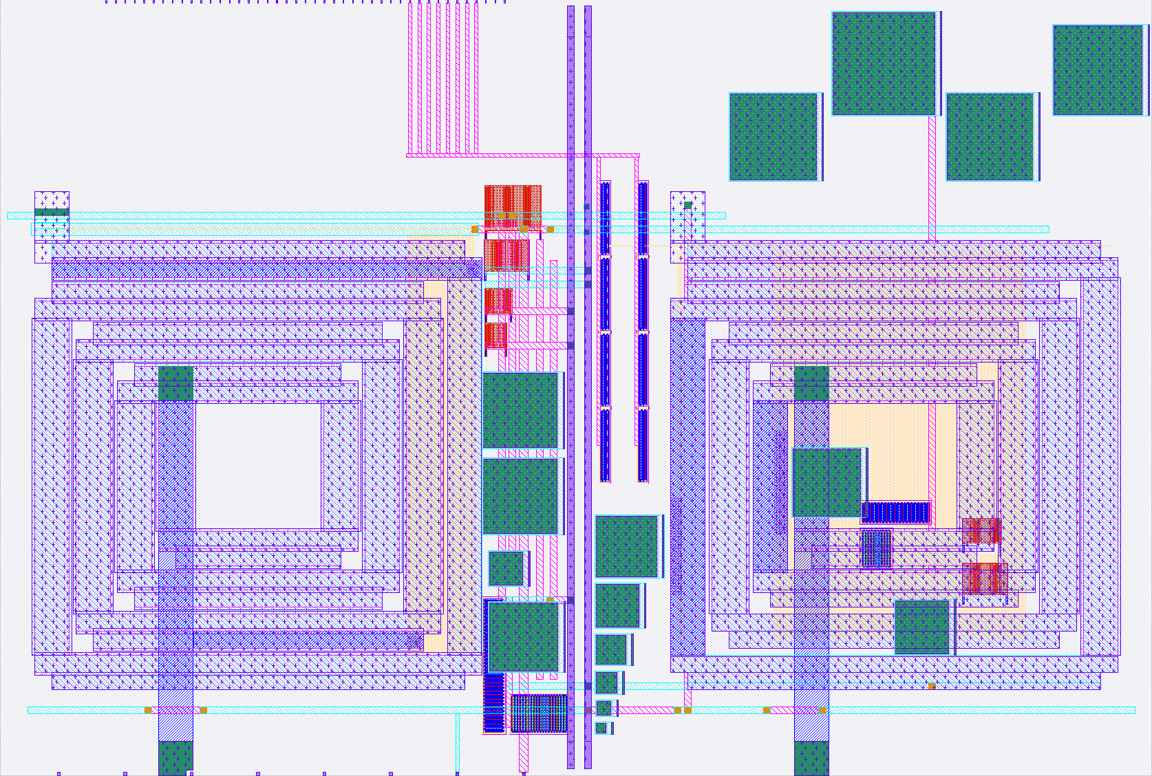
- Description: v7 = v2 baseline + PGS strip + symmetric DELTA=0.8 in-place spiral thicken with cap_mim keepout. Both spirals widened equally (11.6um vertical / 6.6um horizontal), preserving Zhao chiral EP symmetry. Q ~5.7 at 3 GHz, predicted to resolve cv-bits b4-b6.
- GitHub repository
- Open in 3D viewer
- Clock: 0 Hz
How it works
This is an analog chiral exceptional-point (EP) sensor built around two nominally-matched on-chip LC tanks at ~2.7 GHz, coupled in one direction through an NMOS source follower (Mf) and a coupling MIM cap (Cc). Following Zhao et al., the unidirectional coupling places the two-mode system on the exceptional-point line of its eigen-spectrum; a small capacitive perturbation ε on the V1 tank then produces a frequency splitting Δf in the V2 spectrum that scales as Δf ∝ √ε, giving substantial sensitivity gain over a conventional reciprocally-coupled resonator pair.
Block diagram
   ua[0] ── L1 ── V1 ──┬──CT1── VGND        ┌── L2 ── V2_in ──┬── CT2 ── VGND
                       │                    │                 │
                       └── Cv-array (8b) ──┘ ↑                ├── Cc
                       │                     │                │
                       Cac_in                ↑                ↓
                       │                  (one-way)         Vfo (Mf source)
                       Mf gate             coupling          ↑
                       (source follower)                     ┘

                                                          V2_in ── Mout (V2 buffer) ── ua[1]
- L1, L2 — custom 130 × 130 µm square spirals on m4+m3+m2 stack; L = 1.351 nH, Q ≈ 15 (FastHenry-extracted).
- CT1, CT2, Cc — MIM caps tuned for the Zhao-exact EP point at κ = 0.3125, sized for the L = 1.351 nH tank.
- 8-bit cv-array — binary-weighted MIM caps (20, 40, 80, 160, 320, 640,
1280, 1280 fF) switched in via LVT NMOS. Asserting
ui_in[i]adds the i-th bit to the V1 tank. - Source-follower Mf — W = 400 µm × L = 0.15 µm, 80 fingers — drives Vfo with V1's signal, capacitively coupled to the V2 tank through Cc. This is the unidirectional element: V1 → V2, but not V2 → V1.
- V2 output buffer (Mout) — W = 200, nf = 40 source follower; isolates the V2 tank from the bench probe (5 pF + 50 Ω) so the two Zhao peaks remain resolvable post-bondwire.
- On-chip bias dividers — poly resistor stacks generate Vbn = 1.20 V (source-follower tail) and Vbmid = 1.50 V (gate-bias for Cac coupling). No external bias pins required.
Analog pinout
| Pin | Name | Function |
|---|---|---|
| ua[0] | V1 | V1 LC-tank node. Drive an AC test signal here through 50 Ω; the L1 spiral plus tank caps establish resonance. |
| ua[1] | V2 | V2 LC-tank buffered output. Observe the |
Design verification
- DRC clean (KLayout, sky130A_mr.drc, feol/beol/offgrid all 0).
- LVS topologically equivalent to schematic (225 devices match).
- Schematic-level Monte Carlo (500 trials, ±5 % cap, ±10 % L, ±50 mV bias): 100 % yield in the [0.45, 0.55] target slope band.
- Post-layout robustness: realistic parasitic injection causes a uniform ~0.5 % frequency shift; EP scaling preserved bit-for-bit.
How to test
This is an RF analog sensor. You will need:
- Tiny Tapeout demo board + breakout PCB with u.fl connectors on ua[0] (V1) and ua[1] (V2). The u.fl jacks are RF-rated to 6 GHz.
- A vector network analyzer that reaches at least 3 GHz with > 60 dB dynamic range. A Keysight P5004A (9 kHz – 20 GHz, 135 dB DR) is ideal. An Analog Discovery 3 will not work — its 30 MHz bandwidth is far below the chip's 2.7 GHz operating point.
- VDPWR = 1.8 V, all
ui_inpins routed from a microcontroller or manual switches to set the cv-array perturbation code.
Procedure
- Power up the chip. Bias generation is on-chip, no setup required.
- Connect VNA port 1 to ua[0], port 2 to ua[1]. Calibrate.
- Sweep S21 magnitude from 1.5 GHz to 4.5 GHz with
ui_in = 0x00. Locate the resonance — expected near 2.71 GHz. This is the EP-degenerate peak (κ tuned to put the two modes coincident). - Step the cv-array code:
ui_in = 0x01, 0x02, 0x04, 0x08, 0x10, 0x20, 0x40, 0x80, 0xC0. - For each code, locate two local peaks in |S21|^2 and record their separation Δf.
- Plot log(Δf / f₀) vs log(ε) where ε = Ce / (2 C_total). The slope should be ≈ 0.5 ± 0.05 across the operating window — the canonical EP signature.
If the slope departs significantly from 0.5, the chip is operating away from the EP (κ off-target), but the cv-array sweep is still informative as a relative perturbation indicator.
External hardware
- Tiny Tapeout breakout PCB (u.fl variant; supports RF-rated probing).
- Microcontroller (Pi Pico on the demo board is fine) or manual switches
to drive
ui_in[7:0]. - Vector network analyzer (Keysight P5004A or equivalent).
- Two SMA → u.fl pigtails.
IO
| # | Input | Output | Bidirectional |
|---|---|---|---|
| 0 | b0 (cv-array LSB; 20 fF, eps=0.0055) | ||
| 1 | b1 (40 fF, eps=0.011) | ||
| 2 | b2 (80 fF, eps=0.022; lowest resolved point) | ||
| 3 | b3 (160 fF, eps=0.044; Zhao window lower edge) | ||
| 4 | b4 (320 fF, eps=0.088; within Zhao window) | ||
| 5 | b5 (640 fF, eps=0.176; within Zhao window) | ||
| 6 | b6 (1280 fF, eps=0.352; above Zhao window) | ||
| 7 | b7 (cv-array MSB; 1280 fF) |
Analog pins
ua | PCB Pin | Internal index | Description |
|---|---|---|---|
| 0 | B4 | 10 | V1 (V1 LC tank; RF probe drive and observe at 50 ohm) |
| 1 | B5 | 11 | V2 (V2 LC tank; observe peak split) |