421 QAMER CryptoUART: Encrypted UART with LED Status
421 : QAMER CryptoUART: Encrypted UART with LED Status
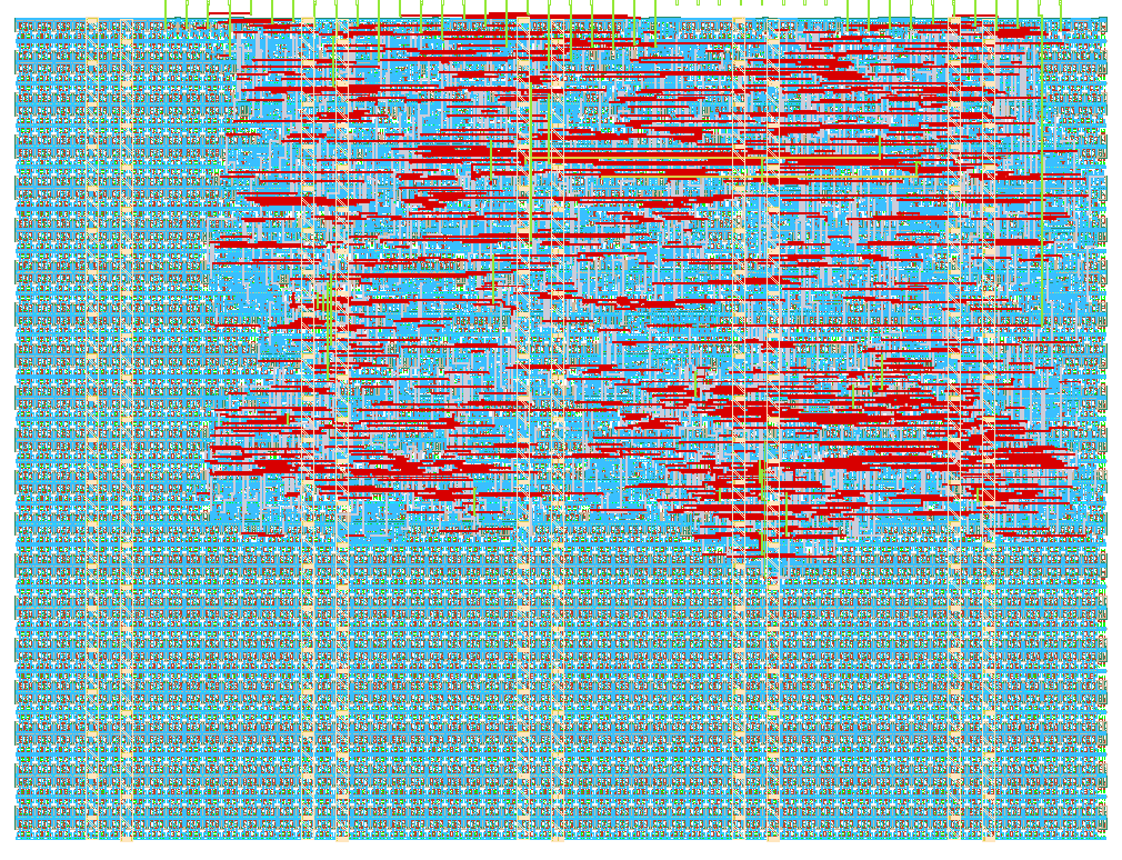
- Author: QAMER
- Description: UART echo with LFSR-based byte encryption and LED activity status.
- GitHub repository
- Open in 3D viewer
- Open in Tiny Tapeout Explorer
- Clock: 50000000 Hz
How it works
QAMER CryptoUART is an encrypted UART demonstration that receives serial data, echoes the received plaintext byte, and then transmits an encrypted version of the same byte.
The design operates at a default clock frequency of 50 MHz and a UART baud rate of 9600.
The 8-bit ui_in input is used as follows:
ui_in[0]is the UART RX input.ui_in[7:1]provides a 7-bit key seed used to initialize the LFSR.
After reset, the LFSR is initialized from the 7-bit key seed. For each received UART character, the current 8-bit LFSR keystream value is XORed with the received byte:
ciphertext = plaintext XOR keystream
The design then:
- Receives a UART byte on
ui_in[0]. - Generates the corresponding encrypted byte using the LFSR keystream.
- Echoes the original plaintext byte through
uo_out[0]. - Transmits the encrypted ciphertext byte through
uo_out[0]. - Updates the LFSR for the next received character.
- Updates the four LED status outputs after each received character.
The four LED outputs build up as characters are received:
- Character 1:
0001 - Character 2:
0011 - Character 3:
0111 - Character 4:
1111
After four characters, the LED sequence starts again with the next group.
Additional status signals are provided on uo_out:
uo_out[5]: RX valid pulseuo_out[6]: UART TX busy statusuo_out[7]: Ciphertext valid pulse
The encrypted byte is also continuously available on uio_out[7:0].
The uio_oe signal is fixed to 8'hFF, so all eight uio pins operate
as outputs.
How to test
Connect a UART transmitter to ui_in[0] and use the default UART settings:
- Clock: 50 MHz
- Baud rate: 9600
- Data: 8 bits
- Start bit: 1
- Stop bit: 1
Provide the 7-bit encryption key through ui_in[7:1]. The key is sampled
when the design initializes after reset.
For example, the supplied functional test uses:
KEY_SEED = 7'h55
and transmits the characters:
A(0x41)B(0x42)
For each character, the design first sends the plaintext byte back through the UART TX output and then sends the corresponding encrypted byte.
The expected ciphertext is calculated using the LFSR keystream:
ciphertext = plaintext XOR keystream
The ciphertext can also be observed directly on uio_out[7:0].
The four LED outputs indicate the number of characters received within the current group of four. The RX-valid and ciphertext-valid signals can be used as one-cycle indicators when the corresponding data becomes available.
The automated Cocotb testbench verifies reset behavior, UART plaintext
echo,
ciphertext generation, LFSR progression, LED status, the live ciphertext
output, and the uio_oe configuration.
External hardware
No external hardware is required for simulation.
For physical demonstration, a standard USB-to-UART adapter can be connected to the UART RX/TX signals. The four LED status outputs can be connected to LEDs through appropriate current-limiting circuitry if the target hardware does not already provide LEDs.
The encryption key is provided through the seven available ui_in[7:1]
input pins.
IO
| # | Input | Output | Bidirectional |
|---|---|---|---|
| 0 | UART_RXD | UART_TXD | CIPHERTEXT[0] |
| 1 | KEY_SEED[0] | LED[0] | CIPHERTEXT[1] |
| 2 | KEY_SEED[1] | LED[1] | CIPHERTEXT[2] |
| 3 | KEY_SEED[2] | LED[2] | CIPHERTEXT[3] |
| 4 | KEY_SEED[3] | LED[3] | CIPHERTEXT[4] |
| 5 | KEY_SEED[4] | RX_VALID | CIPHERTEXT[5] |
| 6 | KEY_SEED[5] | TX_BUSY | CIPHERTEXT[6] |
| 7 | KEY_SEED[6] | CIPHER_VALID | CIPHERTEXT[7] |