354 TinyDMA: A Descriptor-Based Dual-PSRAM Memory Mover
354 : TinyDMA: A Descriptor-Based Dual-PSRAM Memory Mover
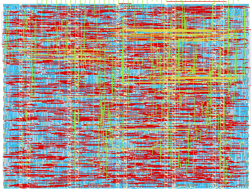
- Author: bennett_lahn
- Description: TinyDMA bulk-copies between dual QSPI PSRAM using in-memory descriptors
- GitHub repository
- Open in 3D viewer
- Open in Tiny Tapeout Explorer
- Clock: 66000000 Hz
TinyDMA: A Descriptor-Based Dual-PSRAM Memory Mover
How it works
TinyDMA is an asychronous memory mover targeting the Tiny Tapeout QSPI PMOD. It uses chains of memory-based descriptors to transfer memory between PSRAM chips (no flash support).
After the host pulses START, the ASIC copies bytes between two PSRAM chips using 11-byte in-memory transfer control descriptors (TCDs).
Each TCD names a source pointer, destination pointer, length, next-TCD pointer, and control flags. Flags indicate the write source/destination, device location for next TCD pointer and QUIT if that chain is the last in the sequence.
The first TCD is always at address 0 on PSRAM 0. Same-device and cross-device copies are supported. The ASIC does not read/write to the PMOD flash, but the MCU can still use it by raising BUS_REQ (ui_in[2]) and waiting for BUS_GNT (uo_out[1]).
For an in-depth description of the architecture, firmware, and verification, see the full TinyDMA documentation.
Host pins:
ui_in[0]START - accepted only while idle andBUS_REQis lowui_in[2]BUS_REQ - MCU wants the QSPI busuo_out[0]DONE - high whenever the DMA is idleuo_out[1]BUS_GNT - MCU may driveuiouio_out- QSPI PMOD
Infinite TCD chains should be avoided. Terminate using rst_n. Target clock is 66 MHz; SCK is clk/2.
How to test
The associated GitHub repo has MicroPython firmware under firmware/, including an existing testbench.
One-time setup
- Set
config.inion the board forASIC_RP_CONTROLandclock_frequency = 66e6. - From a PC (WSL/Linux):
pip install mpremote, then copy firmware and reset:
 mpremote fs cp -r firmware :/firmware
 mpremote reset
- Connect the QSPI PMOD and enable this design on the mux (
tt_um_lahnb_sgdma).
Interactive REPL
Open the USB serial REPL, then:
import firmware.session as session
session.init("tt_um_lahnb_sgdma")   # mux, 66 MHz clk, reset, idle check
session.bring_up_psram()            # SPI reset + Enter Quad on both RAMs
session.status()
Run one memory copy using REPL
Minimal smoke test (8 bytes from PSRAM0 0x000100 to 0x000200, head TCD at 0, quit TCD at 0x000010):
from firmware.tcd import Tcd, encode_tcd
from firmware.link import b64encode, b64decode

src, dst, quit_slot = 0x000100, 0x000200, 0x000010
session.write_span(0, src, b64encode(bytes(range(8))))
session.write_span(0, 0, b64encode(encode_tcd(Tcd(
    src_ptr=src, dest_ptr=dst, transfer_len=8,
    next_tcd=quit_slot, src_device=0, dest_device=0, next_device=0))))
session.write_span(0, quit_slot, b64encode(encode_tcd(Tcd(quit=True))))
session.start_and_wait()
line = session.read_span(0, dst, 8)
dest = b64decode(line.split(" ", 1)[1])
# expect dest == bytes(range(8))
device:0= PSRAM A,1= PSRAM B.session.write_span(device, addr, b64_data)- Writes decoded bytes ataddr. Each call takes BUS_REQ, writes in small chunks, then releases the bus again.session.read_span(device, addr, length)- Reads PSRAM. Returns anOK <base64>line (decode the part afterOKwithfirmware.link.b64decode).session.start_and_wait()- pulses START and waits until DONE rises.
Automated tests from the host PC
All hardware tests are in hil/ and use the included reference model. From the repo root (after using source test/env.sh if using the project venv):
pytest hil/tests/ -v --target=fpga        # builds/uploads bitstream, then runs on Tiny Tapeout FPGA
pytest hil/tests/ -v --target=asic        # same tests on silicon
python -m hil --target=asic               # interactive menu for selecting test cases
The MCU host builds TCDs, installs memory over QPI, pulses START, dumps memory contents, and compares against a reference model. Full API and bus rules: docs/human/architecture/firmware.md.
External hardware
- Tiny Tapeout QSPI PMOD with dual APS6404L (or compatible) PSRAM.
IO
| # | Input | Output | Bidirectional |
|---|---|---|---|
| 0 | START | DONE | FLASH_CS |
| 1 | BUS_GNT | SIO0 | |
| 2 | BUS_REQ | SIO1 | |
| 3 | SCK | ||
| 4 | SIO2 | ||
| 5 | SIO3 | ||
| 6 | RAM_A_CS | ||
| 7 | RAM_B_CS |