554 Hamming(7,4) encoder/decoder (IEEE)
554 : Hamming(7,4) encoder/decoder (IEEE)
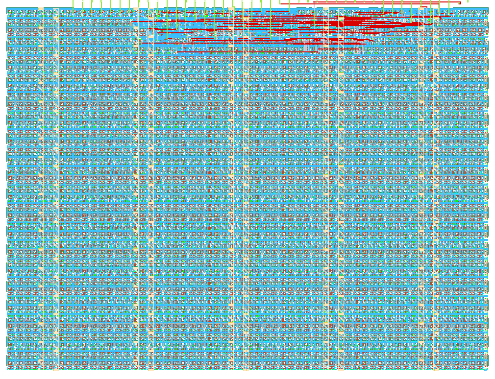
- Author: Esaú Quispe Checca
- Description: Encodes a 4-bit word into a 7-bit Hamming(7,4) codeword, injects a single-bit error, then detects and corrects it — Equipo Triada CEG
- GitHub repository
- Open in 3D viewer
- Open in Tiny Tapeout Explorer
- Clock: 100000 Hz
How it works
The design implements a Hamming(7,4) encoder, a simulated single-bit channel error, and a
decoder/corrector, all in one combinational block registered on clk:
- Encoder:
ui_in[3:0]is treated as a 4-bit data word (d1..d4). Three parity bits (p1,p2,p3) are computed and interleaved with the data to form the 7-bit codeword using the standard 1-indexed layout1=p1 2=p2 3=d1 4=p3 5=d2 6=d3 7=d4. - Error injection:
ui_in[6:4]selects a codeword bit position (1-7) to flip, simulating a transmission error.0means no error is injected. - Decoder: the three parity checks are recomputed on the (possibly corrupted) codeword to produce a 3-bit syndrome. A non-zero syndrome points directly at the corrupted bit position, which is flipped back to recover the original codeword.
- Outputs:
uo_out[3:0]is the corrected 4-bit data (equal to the original input for any single injected error),uo_out[4]is an error flag, anduio_out[6:0]exposes the raw transmitted/received codeword bit-by-bit (uio_out[i]= codeword positioni+1) for inspection on a logic analyzer or in the testbench waveform.
Everything is registered on clk with a synchronous active-low reset (rst_n), so the outputs
reflect the inputs one clock cycle after they are applied.
How to test
Drive ui_in[3:0] with the 4-bit word to encode and ui_in[6:4] with the bit position (1-7)
to corrupt (or 0 for a clean channel), wait one clock cycle, then check:
uo_out[3:0]equals the originalui_in[3:0](Hamming(7,4) always corrects a single-bit error).uo_out[4]is1whenever an error was injected (ui_in[6:4] != 0) and0otherwise.uio_out[6:0]shows the corrupted codeword actually "on the wire" before correction.
test/test.py sweeps all 16 data words against all 8 error positions (no error + each of the
7 possible single-bit flips) and asserts correct recovery in every case.
External hardware
None - this project only exercises the dedicated and bidirectional I/O pins directly.
IO
| # | Input | Output | Bidirectional |
|---|---|---|---|
| 0 | data_in[0] | data_out[0] | codeword[1] (p1) |
| 1 | data_in[1] | data_out[1] | codeword[2] (p2) |
| 2 | data_in[2] | data_out[2] | codeword[3] (d1) |
| 3 | data_in[3] | data_out[3] | codeword[4] (p3) |
| 4 | err_pos[0] | error_flag | codeword[5] (d2) |
| 5 | err_pos[1] | codeword[6] (d3) | |
| 6 | err_pos[2] | codeword[7] (d4) | |
| 7 |