427 4-Input Signed Neuron / Perceptron
427 : 4-Input Signed Neuron / Perceptron
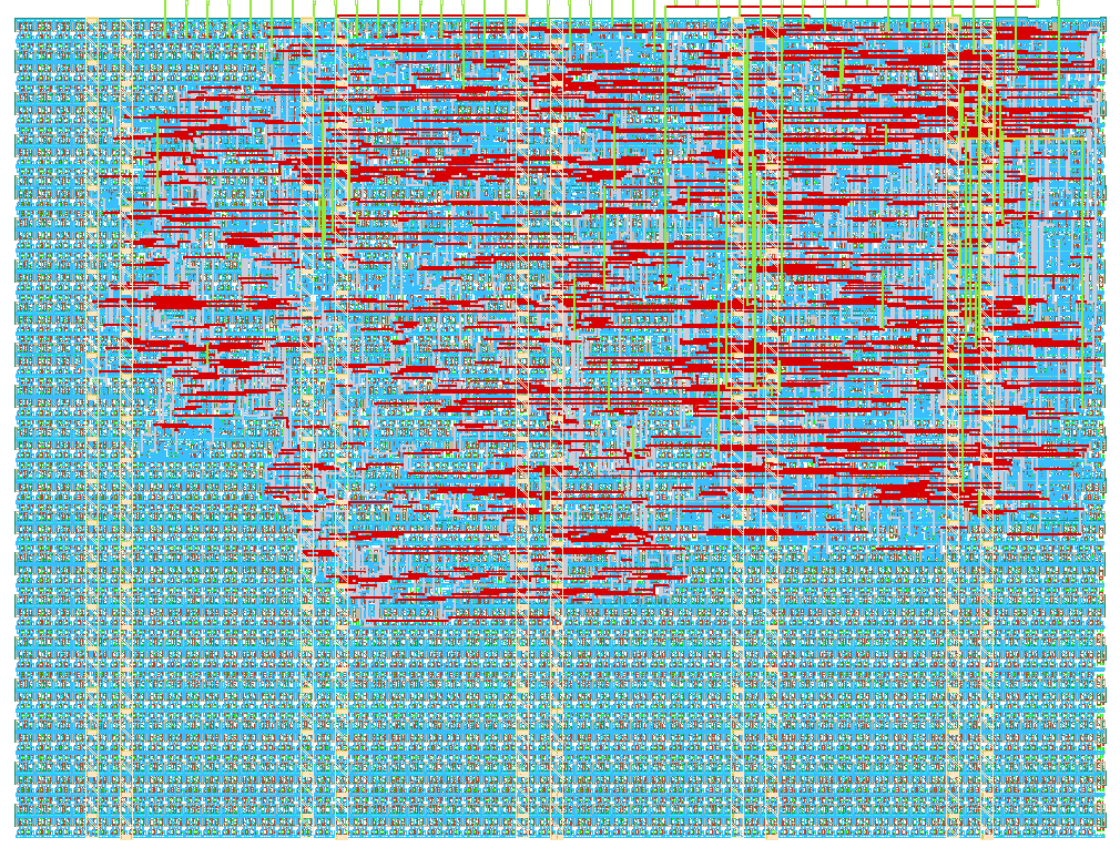
- Author: Mohammad Musharaf Qureshi
- Description: Compact 4-input signed perceptron accelerator with ReLU activation and 8-bit output saturation.
- GitHub repository
- Open in 3D viewer
- Open in Tiny Tapeout Explorer
- Clock: 50000000 Hz
How it works
The 4-Input Signed Neuron / Perceptron is a compact hardware accelerator that calculates a weighted sum of four signed inputs and applies a ReLU activation function with 8-bit output saturation.
The neuron performs:
y = w0×in0 + w1×in1 + w2×in2 + w3×in3 + bias
The four weights, four inputs, and bias are stored internally as 6-bit two's-complement values. The signed 6-bit range is:
-32 to +31
A single shared 6×6 signed multiplier is reused for all four weight-input multiplications. The four products are calculated sequentially and accumulated in a 16-bit accumulator. After the four multiplications, the stored bias is added.
The result then passes through a ReLU activation and an 8-bit saturation stage:
if result < 0
    output = 0

else if result > 255
    output = 255

else
    output = result
Therefore, the final output is always between 0 and 255.
Register Map
The registers are written through ui_in[5:0]. The register selected by uio_in[3:0] is updated when uio_in[4] (WR_EN) is asserted.
| Address | Register |
|---|---|
0 |
w0 |
1 |
w1 |
2 |
w2 |
3 |
w3 |
4 |
bias |
5 |
in0 |
6 |
in1 |
7 |
in2 |
8 |
in3 |
All stored values use 6-bit two's-complement representation.
Input and Control Interface
| Signal | Function |
|---|---|
ui_in[5:0] |
6-bit register data |
ui_in[7:6] |
Unused |
uio_in[3:0] |
Register address |
uio_in[4] |
WR_EN — write selected register |
uio_in[5] |
START — start computation |
uio_in[7:6] |
Unused |
When START is asserted, the accelerator enters its sequential computation:
S_IDLE
   │
   │ START
   ▼
S_MAC0
   │
   ▼
S_MAC1
   │
   ▼
S_MAC2
   │
   ▼
S_MAC3
   │
   ▼
S_BIAS
   │
   ▼
S_ACT
   │
   ▼
S_DONE
The shared multiplier performs:
S_MAC0 → w0 × in0
S_MAC1 → w1 × in1
S_MAC2 → w2 × in2
S_MAC3 → w3 × in3
The S_BIAS state adds the bias. The S_ACT state applies ReLU and saturation, and S_DONE indicates that the result is ready.
Output Interface
The final neuron result is available on uo_out[7:0].
Status signals are provided through uio_out:
| Signal | Function |
|---|---|
uio_out[0] |
BUSY — computation is in progress |
uio_out[1] |
DONE — computation is complete |
uio_out[7:2] |
0 |
The corresponding output-enable signals are:
uio_oe[1:0] = 1
uio_oe[7:2] = 0
How to test
First apply an active-low reset using rst_n and keep ena high.
1. Write the weights, inputs, and bias
For each register:
- Place the 6-bit two's-complement value on
ui_in[5:0]. - Place the register address on
uio_in[3:0]. - Assert
uio_in[4](WR_EN). - Apply a clock edge.
- Deassert
WR_EN.
For example, to write w0 = 3:
ui_in[5:0] = 000011
uio_in[3:0] = 0000
uio_in[4] = 1
Negative values are represented using 6-bit two's complement. For example:
-5 = 6'b111011
2. Start the neuron
After all weights, inputs, and bias values have been written, assert:
uio_in[5] = 1
This starts the calculation.
During computation:
uio_out[0] = 1
indicates that the accelerator is busy.
3. Read the result
When computation completes:
uio_out[1] = 1
indicates DONE.
The final ReLU and saturated result can then be read from:
uo_out[7:0]
After START is deasserted, the accelerator returns to the idle state.
Example 1 — Basic Positive MAC
Weights = [1, 2, 3, 4]
Inputs  = [1, 1, 1, 1]
Bias    = 0
Calculation:
1×1 + 2×1 + 3×1 + 4×1 + 0
= 10
Expected output:
10
Example 2 — ReLU
Weights = [-5, -5, -5, -5]
Inputs  = [1, 1, 1, 1]
Bias    = 0
Calculation:
-5×1 + -5×1 + -5×1 + -5×1
= -20
ReLU clamps the negative result to:
0
Expected output:
0
Example 3 — Output Saturation
Weights = [31, 31, 31, 31]
Inputs  = [4, 4, 4, 4]
Bias    = 31
Calculation:
31×4 + 31×4 + 31×4 + 31×4 + 31
= 527
Since the output is saturated to 8 bits:
527 → 255
Expected output:
255
Example 4 — Mixed Signed MAC
Weights = [3, -2, 4, -1]
Inputs  = [10, 5, 2, 3]
Bias    = -5
Calculation:
3×10 + (-2×5) + 4×2 + (-1×3) - 5
= 30 - 10 + 8 - 3 - 5
= 20
Expected output:
20
Example 5 — Minimum Signed Value
The minimum signed 6-bit value is:
-32
For:
Weights = [-32, 0, 0, 0]
Inputs  = [1, 0, 0, 0]
Bias    = 0
the result is:
-32
After ReLU:
0
Expected output:
0
External hardware
No external hardware is required for simulation.
For a physical demonstration, an FPGA, microcontroller, or other digital controller can be used to provide the register address, 6-bit data, write-enable, and start signals.
The uo_out[7:0] output can be connected to a logic analyzer or other digital interface to observe the neuron result.
The uio_out[0] and uio_out[1] signals provide BUSY and DONE status and can be monitored by the external controller.
IO
| # | Input | Output | Bidirectional |
|---|---|---|---|
| 0 | DATA[0] | RESULT[0] | BUSY |
| 1 | DATA[1] | RESULT[1] | DONE |
| 2 | DATA[2] | RESULT[2] | |
| 3 | DATA[3] | RESULT[3] | ADDR[0] |
| 4 | DATA[4] | RESULT[4] | ADDR[1] |
| 5 | DATA[5] | RESULT[5] | ADDR[2] |
| 6 | RESULT[6] | ADDR[3] | |
| 7 | RESULT[7] |