260 TinyQV SoC (Dual Memory Backend)
260 : TinyQV SoC (Dual Memory Backend)
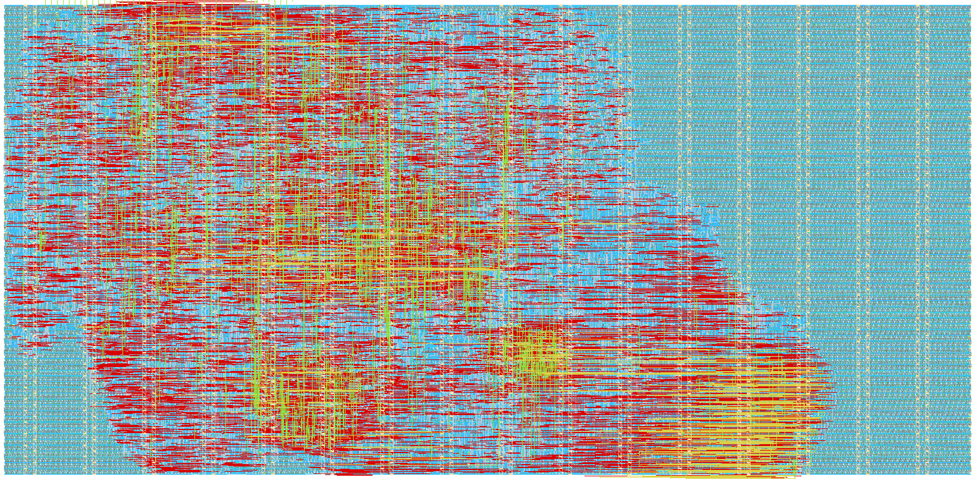
- Author: LKhanh
- Description: TinyQV RISC-V SoC supporting both QSPI PMOD and RP2040 spi-ram-emu
- GitHub repository
- Open in 3D viewer
- Open in Tiny Tapeout Explorer
- Clock: 64000000 Hz
TinyQV SoC (Dual Memory Backend)
A TinyQV RV32EC microcontroller with two memory backends selected by a
reset strap: Quad-SPI Flash/PSRAM via a QSPI PMOD, or single-SPI RAM
emulated on an RP2040 (spi-ram-emu, 23LC512 protocol). System clock
64 MHz. Occupies a 3x2 tile.
How it works
CPU
TinyQV is a 4-bit-serial RV32EC core (M-mode only) with Zcb/Zicond, a
32x16-bit multiplier (mul16), multi-word load/store (lw2/lw4,
sw2/sw4/sw4n), and basic trap/interrupt support (trap vector 0x4,
interrupt vector 0x8). gp is hardwired to 0x01000400, tp to
0x80000000 for fast access to RAM data and peripheral registers.
TIME ticks in microseconds at 64 MHz.
Dual memory backend
ui_in[0] sampled during reset selects the backend (uo_out[1]
mirrors the sampled value):
ui_in[0] |
Mode | Backend |
|---|---|---|
| 0 (default) | Single-SPI | RP2040 spi-ram-emu (23LC512: 0x03 read, 0x02 write) |
| 1 | QSPI PMOD | W25Q128 Flash (continuous read) + 2x APS6404 PSRAM (QPI) |
Single-SPI mode runs the bus at 8 MHz (within the emulator's
12.5–15.6 MHz ceiling) and maps the 25-bit CPU address into the
emulator's 64 KB as {addr[24], addr[14:0]}: instruction fetch lands in
the lower 32 KB (0x0000-0x7FFF), RAM data (e.g. via gp) in the upper
32 KB (0x8000-0xFFFF, so gp = 0x8400). A 48-cycle CS-high cooldown
between transactions gives the RP2040 PIO time to re-arm. QSPI mode uses
the untouched upstream controller (32 MHz bus): Flash must already be in
continuous-read mode (mode bits 0xA0), PSRAM in QPI mode; code executes
from Flash only.
Address map
| Range | Target |
|---|---|
0x0000000-0x0FFFFFF |
Flash (QSPI) / code window (SPI-emu low 32 KB) |
0x1000000-0x17FFFFF |
RAM A (QSPI) / data window (SPI-emu 0x8000-0xFFFF) |
0x1800000-0x1FFFFFF |
RAM B (QSPI) |
0x8000000 |
GPIO output register |
0x8000010 |
UART TX data (write byte to send; read returns busy flag) |
Pinout
| Pin | Function |
|---|---|
ui[0] |
Backend strap (0 = SPI-emu, 1 = QSPI) |
ui[1:2] |
Spare |
ui[3:6] |
External interrupts irq[0:3] |
ui[7] |
Timer interrupt |
uo[0] |
UART TX (115200 baud) |
uo[1] |
Sampled strap mode |
uo[2:7] |
GPIO output bits |
uio[0] |
CS0 (Flash CS / SPI CS) |
uio[1] |
SD0 / MOSI |
uio[2] |
SD1 / MISO |
uio[3] |
SCK |
uio[4] |
SD2 (QSPI only) |
uio[5] |
SD3 (QSPI only) |
uio[6] |
CS1 (RAM A, QSPI only) |
uio[7] |
CS2 (RAM B, QSPI only) |
How to test
RTL simulation (Icarus + cocotb):
cd test && make clean && make        # 2 tests, gate: no <failure> in results.xml
GATES=yes make                        # functional gate-level sim on the hardened netlist
test_spi_ram_emu_mode boots the CPU against a cycle-accurate 23LC512
model (including the CS-recovery check), runs addi/sw/lw/sw/jal, and
asserts 0x42 reaches both SPI RAM (0x8400) and the GPIO pins.
test_qspi_pmod_mode boots the QSPI backend against Flash/PSRAM models
and asserts 0x55 reaches GPIO. Both run at the true 64 MHz tapeout
clock. Hardening (LibreLane 3.0.5, IHP SG13G2): ./tt/tt_tool.py --create-user-config --ihp, then --harden --ihp. Timing closes with
+3.02 ns setup / +0.11 ns hold slack; LVS/DRC/antenna clean.
External hardware
- QSPI PMOD (mole99 design): W25Q128JVSIQ 16 MB Flash + 2x
APS6404L-3SQR-SN 8 MB PSRAM, wired per the
uiotable above. - RP2040 board running
spi-ram-emufor single-SPI mode (4 wires: CS/MOSI/MISO/SCK touio[0:3]), plus a USB-UART tap onuo[0]for console output.
Post-tapeout bring-up (pending tasks)
- [ ] RP2040 emulator firmware: fork
spi-ram-emuto preload the RISC-V binary intoemu_ram[0..0x7FFF](code window) before callingsetup_simulated_sram(); hold the TinyQV board in reset until the preload is done, then release. Demo programs must fit 32 KB code with data addressed viagpin the upper 32 KB. - [ ] RP2040 wiring/clock: connect CS/MOSI/MISO/SCK to
uio[0:3], tieui_in[0]low, confirm the SPI clock stays within the emulator's ceiling (RTL divides to 8 MHz at 64 MHz system clock; the 48-cycle CS cooldown is already enforced in RTL). - [ ] QSPI PMOD provisioning: pre-program the Flash image AND its
continuous-read mode bits (
0xA0) before power-on (TinyQV cannot enter the mode itself); issue the PSRAM QPI-mode entry sequence at board power-up; tieui_in[0]high. - [ ] Board console: 115200 baud tap on
uo[0]; GPIO observation onuo_out[7:2]; verify theuo_out[1]strap indicator matches the intended backend before debugging anything else.
IO
| # | Input | Output | Bidirectional |
|---|---|---|---|
| 0 | strap_mode (0=SPI emu, 1=QSPI PMOD) | uart_tx | CS0 / SPI_CS |
| 1 | spare | strap_mode_out | SD0 / MOSI |
| 2 | spare | gpio[2] | SD1 / MISO |
| 3 | irq[0] | gpio[3] | SCK |
| 4 | irq[1] | gpio[4] | SD2 |
| 5 | irq[2] | gpio[5] | SD3 |
| 6 | irq[3] | gpio[6] | CS1 (RAM A) |
| 7 | timer_irq | gpio[7] | CS2 (RAM B) |