261 SEQ8 Programmable Sequencer
261 : SEQ8 Programmable Sequencer
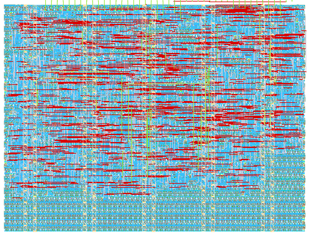
- Author: JET
- Description: 8-instruction programmable sequencer driving 8 output pins
- GitHub repository
- Open in 3D viewer
- Open in Tiny Tapeout Explorer
- Clock: 10000000 Hz
How it works
SEQ8 is a very small programmable sequencer: an 8-instruction state machine that drives 8 output pins.
You shift a program into it over a simple SPI-like port, raise the RUN pin, and it starts executing from address 0. Each instruction either writes a new pattern to the output pins, pauses for a programmable length of time, or jumps, optionally depending on one of two input pins.
The behaviour is not baked into the silicon. One chip can be a traffic light, a stepper-motor driver, an LED chaser, a test pattern generator, or a servo pulse source, depending only on the 8 words you load into it.
Blocks
- Program memory: 8 words x 10 bits, written by the loader, read by the program counter.
- Loader: a shift register clocked by SCK while CS_N is low. Every 10 bits it writes one instruction and auto-increments the write address.
- Tick generator: a 12-bit counter that makes one "tick" every 1, 16, 256 or 4096 clock cycles, chosen by pins
ui[7:6]. WAIT counts ticks. - Core: a 3-bit program counter, an 8-bit wait counter and the 8-bit output register.
Instruction set
Every instruction is 10 bits: a 2-bit opcode and an 8-bit operand.
| Opcode | Name | Operand | Effect |
|---|---|---|---|
00 |
OUT | 8-bit value | drive uo_out |
01 |
WAIT | count | pause for (count + 1) ticks |
10 |
JMP | cond[7:6], addr[2:0] |
jump; see below |
11 |
NOP | - | do nothing |
Jump conditions (operand bits 7:6):
| cond | Behaviour |
|---|---|
00 |
always jump to addr |
01 |
jump to addr if IN0 (ui[4]) is high, otherwise continue |
10 |
jump to addr if IN1 (ui[5]) is high, otherwise continue |
11 |
HALT: stop and hold the current outputs |
The program counter is 3 bits, so it wraps from address 7 back to 0 by itself. A program that fills all 8 words loops with no JMP at all. A shorter program must end with a JMP or HALT, otherwise it runs on into memory that was never loaded.
Tick speed
ui[7:6] |
Clock cycles per tick |
|---|---|
00 |
1 |
01 |
16 |
10 |
256 |
11 |
4096 |
For example, with ui[7:6] = 11 and a 4096 Hz clock, one tick is one second, so WAIT 9 lasts 10 seconds.
Loading a program
- Hold RUN low. The core stays in reset while you load.
- Pull CS_N low. The write address resets to 0.
- For each instruction, shift 10 bits on the rising edge of SCK, most significant bit first. Instructions are written back to back starting at address 0.
- Raise CS_N.
- Set
ui[7:6]for the tick speed, then raise RUN. Execution starts at address 0.
The chip samples SCK, MOSI and CS_N with its own clock, so keep every pin steady for at least 4 clock cycles per step. In practice, load the program with a fast clock (for example 1 MHz), then switch to the slow clock you want for running.
Dropping RUN low at any time clears the outputs and rewinds to address 0, so you can restart a program without reloading it.
How to test
The easiest way is with the RP2350 on the demo board driving the load pins in MicroPython. Shift in a program, raise RUN, and watch the output pins.
A worked example, a two-direction traffic light, is in tools/traffic.s along with an assembler (tools/seq16asm.py) that turns the source into the words you shift in.
For a quick manual check without any software, load this two instruction program and confirm that all eight uo_out pins go high: OUT 0xFF (0x0FF), HALT (0x2C0).
The cocotb test suite in test/ covers reset behaviour, the loader, WAIT timing, the tick speed select, both conditional jumps, program counter wraparound and a full traffic-light sequence.
External hardware
None required. LEDs with series resistors on the output pins make the behaviour visible. The design can also drive a 7-segment display, motor driver inputs, or anything else that takes logic-level signals.
IO
| # | Input | Output | Bidirectional |
|---|---|---|---|
| 0 | SCK - program load clock | OUT0 | |
| 1 | MOSI - program load data | OUT1 | |
| 2 | CS_N - program load select, active low | OUT2 | |
| 3 | RUN - high to execute, low to reset the core | OUT3 | |
| 4 | IN0 - branch input 0 | OUT4 | |
| 5 | IN1 - branch input 1 | OUT5 | |
| 6 | TICK0 - tick speed select, low bit | OUT6 | |
| 7 | TICK1 - tick speed select, high bit | OUT7 |