104 IEEE Bandgap Reference
104 : IEEE Bandgap Reference
- Author: Paweł Pobłocki
- Description: IHP Analog Academy BG design example
- GitHub repository
- Open in 3D viewer
- Open in Tiny Tapeout Explorer
- Clock: 0 Hz
How it works
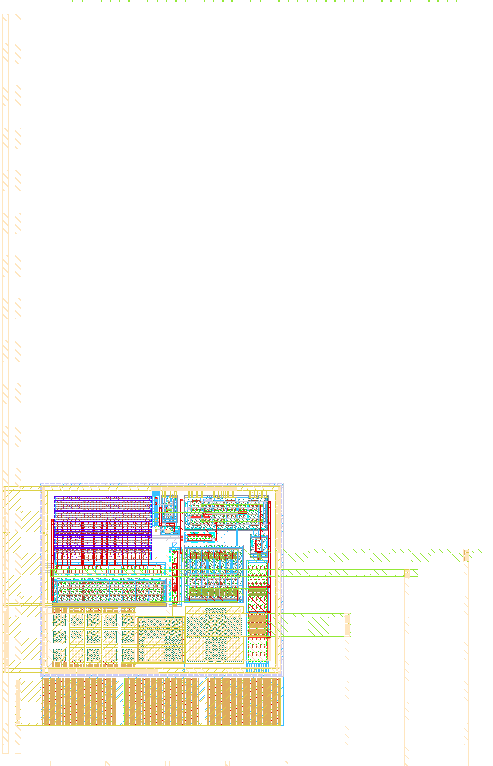
It is simple band gap reference. Design was adopted from https://github.com/IHP-GmbH/IHP-AnalogAcademy/blob/main/modules/module_1_bandgap_reference/part_3_layout/BGR_layout/final_bandgapreference/full_bandgap_layout_filled.gds. Main work was to insert it correctly into IHP PDK grid and take car of its integration into multi project wafer from Tiny Tapout.
How to test
Connect 5uA current source to Iout to bias opamp. Check if Vbg voltage is bandgap refernece (aorund 600mV). Check if bandgap reference voltage stays at 600mV over full temperature range -40 to 125 Celcius degries.
External hardware
Simple current mirror with potentiometer to set 5uA current should do the work.
IO
| # | Input | Output | Bidirectional |
|---|---|---|---|
| 0 | |||
| 1 | |||
| 2 | |||
| 3 | |||
| 4 | |||
| 5 | |||
| 6 | |||
| 7 |
Analog pins
ua | PCB Pin | Internal index | Description |
|---|---|---|---|
| 0 | C | 0 | iout |
| 1 | D | 1 | Vbg |
| 2 | F | 2 | Vout_amp |