162 UART-SPI-I2C Bridge
162 : UART-SPI-I2C Bridge
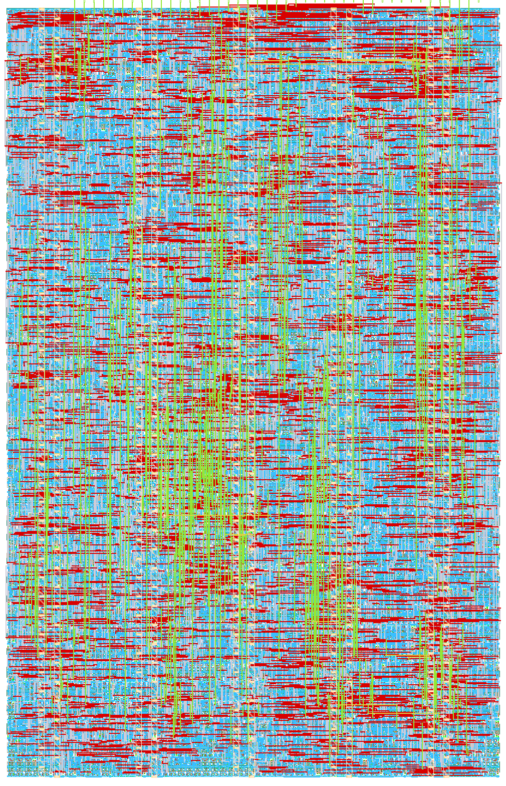
- Author: Catalin Lazar
- Description: UART-controlled protocol bridge with an SPI master (4x CS, configurable CPOL/CPHA) and an I2C master (clock stretching), driven by a command interpreter with FIFO buffering and a memory-mapped register file. Fully testable standalone via UART commands, with a built-in loopback self-test mode.
- GitHub repository
- Open in 3D viewer
- Open in Tiny Tapeout Explorer
- Clock: 10000000 Hz
How it works
A UART command interpreter drives an SPI master (4x chip-select,
configurable CPOL/CPHA) and an I2C master (clock stretching, 7-bit
addressing) over a shared 8-bit memory-mapped register file. UART
RX/TX are FIFO-buffered so bursts of commands or data don't stall the
host. See the top-level README.md for the full opcode table, register
map, pinout, and the "Design history" section on how this ended up on
a 1x2 tile.
How to test
Hold ui_in[2] (loopback_test_en) high and issue an SPI_XFER (opcode
0x03) command over UART at 9600 baud (default): the chip should echo
back exactly the bytes you sent, since MOSI is looped to MISO
internally. Issuing I2C_WRITE in the same loopback mode should
reliably reply with a NACK status byte (no real I2C slave is present),
which exercises the START/ADDRESS/STOP sequencing. Connect a real SPI
or I2C peripheral (with pull-ups on uio[0]/uio[1] for I2C) and drop
loopback_test_en low for full end-to-end testing.
See test/test.py for an automated cocotb testbench covering register
read/write, SPI loopback, I2C NACK detection, and STATUS/RESET.
External hardware
- Optional: any SPI peripheral, wired to
uo_out[1](SCLK),uo_out[2](MOSI),ui_in[1](MISO), and one ofuo_out[6:3](CS). - Optional: any I2C peripheral on
uio[0]/uio[1], with external pull-up resistors (required — the design only drives these lines open-drain low). - A USB-UART adapter on
ui_in[0]/uo_out[0]for sending commands.
IO
| # | Input | Output | Bidirectional |
|---|---|---|---|
| 0 | uart_rx | uart_tx | i2c_scl |
| 1 | spi_miso | spi_sclk | i2c_sda |
| 2 | loopback_test_en | spi_mosi | |
| 3 | spi_cs_n[0] | ||
| 4 | spi_cs_n[1] | ||
| 5 | spi_cs_n[2] | ||
| 6 | spi_cs_n[3] | ||
| 7 | heartbeat_led |