32 6-bit multi function ALU ( eldawly_V2)
32 : 6-bit multi function ALU ( eldawly_V2)
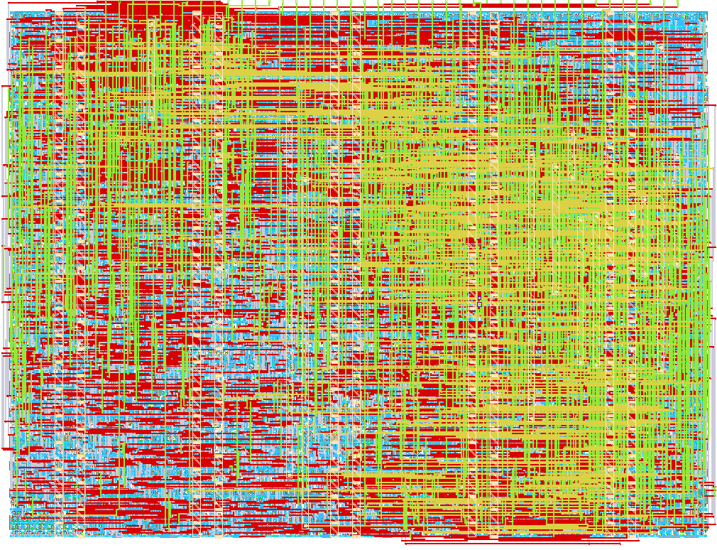
- Author: ziad mokhtar
- Description: 6-bit ALU featuring RCA, CLA, multipliers, logic, shifts, popcount, and comparison operations
- GitHub repository
- Open in 3D viewer
- Open in Tiny Tapeout Explorer
- Clock: 0 Hz
How it works
This project implements tt_um_alu_bns, a 16-bit multi-functional ALU core wrapped
in a byte-serial load/read interface to fit within TinyTapeout's 8-bit pin budget.
ALU core (alu_core) — a purely combinational block that computes all eight
operations in parallel and selects the result by opcode:
| opcode | Operation | sub_op meaning |
|---|---|---|
| 000 | Ripple Carry Adder (RCA) | — |
| 001 | Carry Lookahead Adder (CLA) | — |
| 010 | Array Multiplier (16x16→32) | — |
| 011 | Wallace Tree Multiplier (16x16→32) | — |
| 100 | Logic unit | 00=AND, 01=OR, 10=XOR |
| 101 | Shift / Popcount | 00=shift left, 01=shift right, 10=popcount |
| 110 | Comparator (A vs B) | — |
| 111 | Popcount (forced, ignores sub_op) | — |
All operands, sums, and comparator/logic results are 16-bit; the two multipliers
produce a 32-bit product. Result is always packed into a 32-bit register (upper
bits zero-extended for non-multiply ops), with Cout and Valid flags set alongside it.
Byte-serial wrapper (tt_um_alu_bns) — since ui_in/uio_in are only 8 bits
wide, two 16-bit operands can't be loaded in one clock cycle. Instead, the wrapper
exposes a small register-addressed load/read protocol driven by clk:
ui_in[7:0]= data byte to loaduio_in[7:5]= REG_SEL (which register/action this cycle targets)uio_in[4]= LD (load strobe, sampled on the clock edge)uio_in[1:0]= READ_SEL (which byte of the 32-bit result to output)
REG_SEL values: 000/001 load A's low/high byte, 010/011 load B's low/high
byte, 100 loads the control word (opcode, sub_op, Cin packed into one byte),
and 101 (START) latches A/B/Cin/opcode/sub_op into the combinational core and
captures Result/Cout/Valid into output registers on that same edge.
uo_out continuously shows one byte of the latched 32-bit Result, selected by
READ_SEL. uio_out[3:2] expose Valid and Cout; all other uio_out bits are
unused. uio_oe marks only those two status bits as outputs — every other uio
pin stays an input, since they're used to drive REG_SEL/LD/READ_SEL from outside.
How to test
Each operation takes 6 clock cycles: load A (2 bytes), load B (2 bytes), load control, then START.
- Load A low byte:
uio_in = 8'b000_1_00xx(REG_SEL=000, LD=1),ui_in = A[7:0], pulseclk. - Load A high byte:
uio_in = 8'b001_1_00xx,ui_in = A[15:8], pulseclk. - Load B low byte:
uio_in = 8'b010_1_00xx,ui_in = B[7:0], pulseclk. - Load B high byte:
uio_in = 8'b011_1_00xx,ui_in = B[15:8], pulseclk. - Load control word:
uio_in = 8'b100_1_00xx,ui_in = {2'b0, Cin, sub_op[1:0], opcode[2:0]}, pulseclk. - Start:
uio_in = 8'b101_1_00xx, pulseclk— the core computes and the result is latched.
To read back the 32-bit result, set uio_in[1:0] = READ_SEL (00=bits 7:0, 01=bits
15:8, 10=bits 23:16, 11=bits 31:24, no LD/clock needed — it's combinational) and
read uo_out for each byte. Check uio_out[3] (Valid) and uio_out[2] (Cout) for
the status flags.
Example — 16-bit RCA, A=0x1234, B=0x0001, Cin=0:
load A_LOW=0x34, A_HIGH=0x12, B_LOW=0x01, B_HIGH=0x00, control byte
{Cin=0, sub_op=00, opcode=000} = 8'h00, then START. Expected Result = 0x00001235
(RCA opcode is zero-extended to 32 bits), Cout=0, Valid=1.
External hardware
None — this project has no external hardware dependencies.
IO
| # | Input | Output | Bidirectional |
|---|---|---|---|
| 0 | A[0] | Result[0] | B[0] |
| 1 | A[1] | Result[1] | B[1] |
| 2 | A[2] | Result[2] | B[2] |
| 3 | A[3] | Result[3] | B[3] |
| 4 | A[4] | Result[4] | B[4] |
| 5 | A[5] | Result[5] | B[5] |
| 6 | Cin | Result[6] | Opcode[1] |
| 7 | Opcode[0] | Result[7] | Opcode[2] |