521 tt_um_adxl362_test
521 : tt_um_adxl362_test
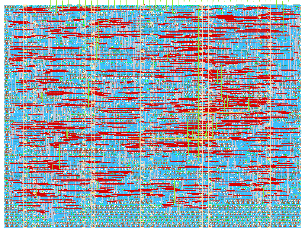
- Author: Barry Kane
- Description: A SPI to UART bridge for an ADXL362
- GitHub repository
- Open in 3D viewer
- Open in Tiny Tapeout Explorer
- Clock: 50000000 Hz
How it works
Reads an ADXL362 accelerometer over SPI and streams the samples as text on a UART.
On reset it reads DEVID_AD and checks it returns 0xAD, raising uo[1] "dev_ok" if so. POWER_CTL is then written to enter measurement mode. Then @10Hz it reads XDATA_L..ZDATA_H and prints a line as follows over UART @ 115200 baud:
X=00f5 Y=ffee Z=03f1
Values are the 12-bit two's complement readings sign-extended to 16 bits, in hex. It uses the default +/- 2 g range.
SPI is 1MHz mode 0 with the ADXL362's three-byte command header.
ui_in is unused. uo[7:2] are driven low.
How to test
Plug a Pmod ACL2 into the bidirectional PMOD connector, set the clock to 50 MHz, and press reset.
uo[0] follows the recommended UART pinout, so the demo board's RP2040 can bridge it to USB. Open that serial port at 115200 8N1.
Lines then appear ten times a second. Lying flat, one axis reads roughly +/- 1000 (1 g) and the other two sit near zero. Tilting the board should result in a change in the output.
uo[1] "dev_ok" can be connected to an LED or read through tt-commander-app
External hardware
List external hardware used in your project (e.g. PMOD, LED display, etc), if any
Digilent Pmod ACL2 (ADXL362). The UART is on uo[0], the demo board's RP2040 provides the console over USB.
SPI pins follow both the TT recommended SPI pinout and Pmod Interface Type 2, so the ACL2 plugs straight into the bidirectional connector:
tile pin Pmod pin signal uio[0] 1 CS_N uio[1] 2 MOSI uio[2] 3 MISO uio[3] 4 SCK
IO
| # | Input | Output | Bidirectional |
|---|---|---|---|
| 0 | uart_tx | spi_cs_n | |
| 1 | dev_ok | spi_sclk | |
| 2 | spi_mosi | ||
| 3 | spi_miso | ||
| 4 | |||
| 5 | |||
| 6 | |||
| 7 |