714 3-Bit ALU
714 : 3-Bit ALU
- Author: Garima Malhotra
- Description: This circuit implements a 3-Bit Arithmetic Logic Unit (ALU) capable of performing arithmetic and logical operations on two 3-bit binary numbers.
- GitHub repository
- Open in 3D viewer
- View in Wokwi
- Clock: 0 Hz
3-Bit ALU
1. Overview
This circuit implements a 3-Bit Arithmetic Logic Unit (ALU) capable of performing arithmetic and logical operations on two 3-bit binary numbers.
The ALU supports:
- Addition
- Subtraction
- Bitwise OR
- Bitwise AND
The result is displayed on a 7-segment display in hexadecimal.
Inputs and Outputs
The input pins are configured as follows:
| Pin | Signal | Description |
|---|---|---|
| IN0 | a[2] |
MSB of input a |
| IN1 | a[1] |
Middle bit of input a |
| IN2 | a[0] |
LSB of input a |
| IN3 | b[2] |
MSB of input b |
| IN4 | b[1] |
Middle bit of input b |
| IN5 | b[0] |
LSB of input b |
| IN6 | s[1] |
MSB of select input s |
| IN7 | s[0] |
LSB of select input s |
Where:
a[2:0]andb[2:0]are the two 3-bit binary operands.s[1:0]is the select input used to choose the ALU operation.
Output Display
The ALU output is displayed on a 7-segment display in hexadecimal.
For subtraction operations that produce a negative result:
- The decimal point (
DP) on the 7-segment display is used as a negative sign indicator DP = 1indicates the displayed value is negativeDP = 0indicates the displayed value is positive
Example:
a = 001₂ (1)
b = 011₂ (3)
s = 01 (subtract)

1 - 3 = -2
The display will show 2 with the decimal point illuminated to indicate the result is -2

2. ALU Operations
The select line can be configured to perform the following operations -
| Select Value | Operation |
|---|---|
00 |
a[2:0] + b[2:0] |
01 |
a[2:0] - b[2:0] |
10 |
a[2:0] OR b[2:0] |
11 |
a[2:0] AND b[2:0] |
s[1] essentially selects the type of operation
s[1] = 0→ Arithmetic operationss[1] = 1→ Logic operations
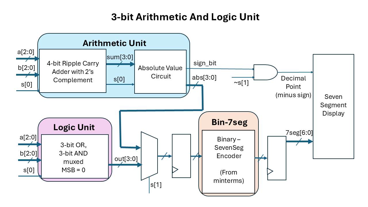
3. Architecture
The ALU is divided into two main sections:
-
Arithmetic Unit
- Performs addition and subtraction
- Implemented using a ripple-carry adder
- Subtraction is achieved using 2’s complement arithmetic
-
Logic Unit
- Performs bitwise AND and OR operations
A multiplexer selects the appropriate output based on the select input s[1:0].
The following is a system diagram of the ALU -
4. Arithmetic Operation
4.1 Arithmetic Unit Interface
The arithmetic unit takes the operands and select lines as inputs and produces both a 4-bit absolute value and a sign indicator for display purposes.
Inputs and Outputs
| Signal | Direction | Description |
|---|---|---|
a[2:0] |
Input | First 3-bit operand |
b[2:0] |
Input | Second 3-bit operand |
s[0] |
Input | Operation select line (addition/subtraction control) |
abs[3:0] |
Output | 4-bit absolute value of the arithmetic result |
sign_bit |
Output | Indicate sign of result from arithmetic (used to drive 7-segment DP) |
4.2 Arithmetic Unit Design
The arithmetic section of the ALU is implemented using a 4-bit ripple carry adder with additional logic to support 2’s complement arithmetic. This stage is followed by an absolute value circuit.
4.2.1 Ripple Carry Adder Structure
The arithmetic unit uses a 4-bit ripple carry adder composed of:
- Three full-adder stages
- One final half-adder stage (without the carry out)
Stage Breakdown
| Stage | Type | Purpose |
|---|---|---|
| Bit 0 | Full Adder | LSB computation |
| Bit 1 | Full Adder | Intermediate computation |
| Bit 2 | Full Adder | MSB of 3-bit operands |
| Bit 3 | Half Adder / XOR Stage | Sign or overflow extension |
The final stage does not propagate a carry-out and is implemented using only an XOR operation. It represents the negative sign for 2's complement, or an overflow in addition.
The subtraction option produces a range of outputs [-7, 7], thus never using the 4th bit. This limited range occurs because this particular ALU doesn't support 2 negative numbers; the first operand 'a' can only be a positive value. Hence this 4th bit is used as the sign bit in 2's complement format, which is later useful in evaluating the absolute value.
However, the addition option produces a range of outputs [0, 14] which overflows into the 4th bit.
Hence MSB = 1 strictly means either
- an overflow in addition or
- a sign bit in subtraction.
Determining whether the MSB = 1 is due to overflow or is sign bit is based on the value of s[0]: whether the user's intent was subtraction or addition.
4.2.2 2's Complement Arithmetic Implementation
2’s Complement allows the same binary adder circuit to perform both addition and subtraction by representing negative numbers in 2’s complement form.
In a 2’s complement number:
- The most significant bit (MSB) acts as the sign bit
0indicates a positive number1indicates a negative number
- Positive numbers are represented normally (unchanged binary form)
- Negative numbers are represented using the 2’s complement method
To convert a binary number into its 2’s complement representation:
- Invert all the bits (change
0s to1s and1s to0s) - Add
1to the result
This approach simplifies digital circuit design because subtraction can be performed using the same hardware as addition.
Flipping the bits
The operand b[2:0] and not (b[2:0]) are passed through a bank of multiplexers controlled by the select line s[0].
The behavior is:
s[0] |
Operation | Value Passed to Adder |
|---|---|---|
0 |
Addition | b |
1 |
Subtraction | ~b |
Therefore:
- During addition, the adder receives
b - During subtraction, all bits of
bare inverted before entering the adder
This implements the first step of 2’s complement subtraction.
Carry-In Control
The select line s[0] is also connected to the carry-in of the ripple carry adder.
Therefore:
s[0] |
Carry-In |
|---|---|
0 |
0 |
1 |
1 |
Additionally, the MSB (4th bit) is set as s[0] XOR carry_in, indicating a negative sign.
So when subtraction is selected:
- The bits of
bare inverted - A
1is added through the carry-in input - The MSB is set to 1
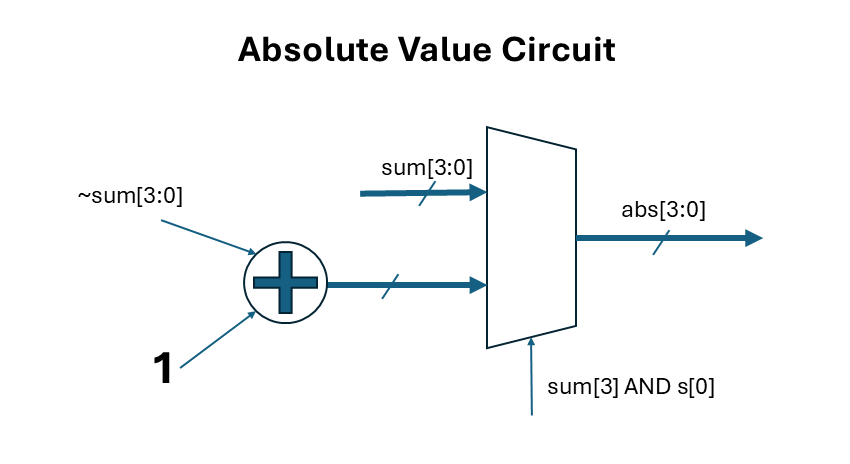
4.2.3 Absolute Value Circuit
To convert the 2's complement representation into absolute value, we first evaluate whether the value from the adder is a negative or positive value.
- The condition where MSB = 1 and subtraction was user intent (s[0]=1; s[1] is common) => negative number. In this case, we need to perform 2’s complement operation of flipping the bits and adding one to get absolute value.
- In other cases, the output from the adder is a positive number, which doesn't need to be further operated upon.
A cascade of half adders is used to add 1 to the inverted bits.
Below is the circuit diagram for the Absolute Value Circuit.
5. Binary to 7 Segment Encoder
The following was the truthe table from binary to displaying it's equivalent hex value in the seven segment display.
| Binary | Hex | ABCDEFG (7SEG) |
|---|---|---|
| 0000 | 0 | 1111110 |
| 0001 | 1 | 0110000 |
| 0010 | 2 | 1101101 |
| 0011 | 3 | 1111001 |
| 0100 | 4 | 0110011 |
| 0101 | 5 | 1011011 |
| 0110 | 6 | 1011111 |
| 0111 | 7 | 1110000 |
| 1000 | 8 | 1111111 |
| 1001 | 9 | 1111011 |
| 1010 | A | 1110111 |
| 1011 | B | 0011111 |
| 1100 | C | 1011110 |
| 1101 | D | 0111101 |
| 1110 | E | 1001111 |
F is not included as it is an unreachable value.
The binary expression for each segment of the display is reduced using karnaugh map and is implemented as a sum-of-products (minterms) in the ALU.
How to test
User can test by setting values of operands a[2:0], b[2:0] and selecting the desired operation using the select lines s[1:0]. The circuit starts in an unknown state, so the seven segment display dispalys a random sequence on startup. It takes 2 clock cycles/ button presses for triggering clock for the input to propagate through to the output.
Example
If:
a = 101₂ (5)
b = 111₂ (7)
Then:
| Select | Operation | Result (Binary) | Result (Hex) |
|---|---|---|---|
00 |
5 + 7 |
1100₂ |
C₁₆ |
01 |
5 - 7 |
1110₂ |
2₁₆ and Decimal Point (indicating negative sign) |
10 |
101 OR 111 |
111₂ |
7₁₆ |
11 |
101 AND 111 |
101₂ |
5₁₆ |
After setting the input switches, trigger the clock twice to see the results on the seven segment display.
External hardware
Seven Segment Display
IO
| # | Input | Output | Bidirectional |
|---|---|---|---|
| 0 | a[2] | 7Seg_A | |
| 1 | a[1] | 7Seg_B | |
| 2 | a[0] | 7Seg_C | |
| 3 | b[2] | 7Seg_D | |
| 4 | b[1] | 7Seg_E | |
| 5 | b[0] | 7Seg_F | |
| 6 | s[1] | 7Seg_G | |
| 7 | s[0] | 7Seg_DP |