968 Audio Wave Generator Chip
968 : Audio Wave Generator Chip
- Author: Rongbin Gu (@rongbin99), Evan Li (@happyredmapleleaf)
- Description: Multi-channel Sound Wave Generator
- GitHub repository
- Open in 3D viewer
- Clock: 28835840 Hz
How it works
2-Channel Sine and Triangle Wave Sound Chip with 8-bit PWM Output.
Two 16-bit registers, written through a parallel bus interface, to control the frequencies of channel 1 (sine) and channel 2 (triangle). Register values go to both sine and triangle wave modules, which uses Direct Digital Synthesis (DDS), to generate 7-bit digital samples at varying frequencies with a sample rate of 28160 Hz. The 7-bit values are added together to an 8-bit sample which is converted to a PWM signal. Each 8-bit sample is converted to four 112640 Hz PWM pulses. The base clock is thus 256x the PWM frequency at 28835840 Hz (~28.84 MHz).
Recommended generated frequency range: 220-1960 Hz
The phase_counter module is simply a 10-bit counter that counts up with the clock and outputs the counter value subsample_phase. Each counter period corresponds to one sample.
The sine module uses CORDIC to algorithmically estimate sine values. The stages of estimation and updating outputs are coordinated with subsample_phase. The triangle module uses Direct Digital Synthesis (DDS) to create a uniform increasing and decreasing ramp waveform with the specified period.
GDS Render
Architecture
Block Diagram
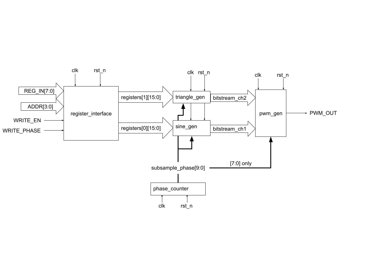
The architecture consists of several key components:
- register_interface: Implements the write protocol and two 16-bit frequency control registers
registers[0]andregisters[1]. - triangle_gen: Generates a triangle waveform into
bitstream_ch2based onregisters[1][11:0]. - sine_gen: Generates a sine waveform into
bitstream_ch1based onregisters[0][11:0]. - phase_counter: Implements a 10-bit counter on
subsample_phase[9:0]used for the timings of all waveform and PWM updates. - pwm_gen: Adds both channels and compares the waveforms against
subsample_phase[7:0]to producepwm_out.
Register map
| Register | Description |
|---|---|
| 0b0000 | freq_ch1* (sine) |
| 0b0001 | freq_ch2* (triangle) |
| 0b0010-1111 | Reserved/Unused |
*only the least significant 12 bits of frequency registers are read.
To calculate register values from frequency f in Hz, use the following formula:
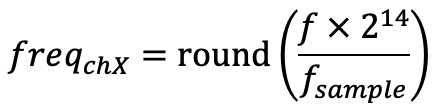
where f<sub>sample</sub> = 28160 Hz, the output sample rate.
Pinout
Clock frequency: 28835840 Hz (~28.8 MHz)
Reset: active low
| # | Input | Output | Bidirectional |
|---|---|---|---|
| 0 | Register bus address[0] | - | Register bus data[0] |
| 1 | Register bus address[1] | - | Register bus data[1] |
| 2 | Register bus address[2] | - | Register bus data[2] |
| 3 | Register bus address[3] | - | Register bus data[3] |
| 4 | Transfer phase | - | Register bus data[4] |
| 5 | Transfer enable | - | Register bus data[5] |
| 6 | Unused | - | Register bus data[6] |
| 7 | Unused | PWM output | Register bus data[7] |
Bus details
To write to registers:
0. Start with enable = 0
- Set address bits, most significant 8 bits of data, and phase to 1 for at least 2 clock cycles.
- Set
enable = 1for at least 2 cycles. When this edge is detected, the most significant 8 bits will be read. - Set
phase = 0for at least 2 cycles. When this edge is detected, the least significant 8 bits will be read. - Set
enable = 0for at least 2 cycles. When this edge is detected, the full register value will be written at the specified address.
If any of these steps are violated, the internal state machine will either:
- if
enable = 1: transition into an error state which can be reset by toggling enable back to 0 - if
enable = 0: discard the ongoing bus transfer and reset to idle state
See src/register_interface.v for the exact details of the bus transfer logic.
Requirements
- Yosys OSS CAD suite: https://github.com/YosysHQ/oss-cad-suite-build
- KiCad (optional, for simulating and exporting DAC frequency response)
- Python modules: numpy, scipy
How to test
Remember to source OSS CAD suite. gtkwave can be used to view output waveforms of tests.
System-Level Tests
cd test/
RTL test:
make -B
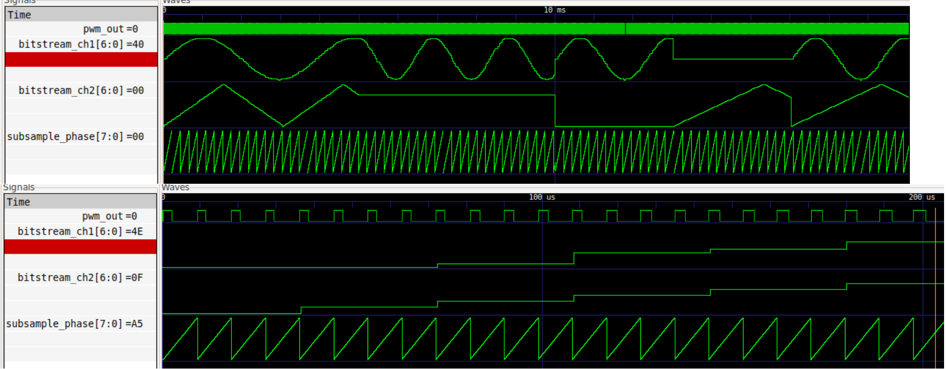
Sample test waveform for all tests in test.py:
Gate-level test (requires hardening first. see Hardening section):
TOP_MODULE=$(cd .. && ./tt/tt_tool.py --print-top-module)
cp ../runs/wokwi/final/pnl/$TOP_MODULE.pnl.v gate_level_netlist.v
make -B GATES=yes
These tests are also run by the TinyTapeout Github Actions.
Block-Level Tests
A cocoTB testbench is used to run tests in Python. Each test uses the following structure:
- Sets up the system clock using cocoTB
Clock. - Initializes all DUT inputs and de-asserts
rst_nafter some cycles. - Drives stimuli into the DUT and runs for several cycles (
await ClockCycles(...)) - Checks the assertions on the outputs to verify the correct behaviour and result.
These are RTL tests only. There are four block-level test directories and a full integration test:
test/tb_pwm_phase- for phase_counter and pwmtest/tb_regs- for register_interfacetest/tb_sine- for sine waveformtest/tb_triangle- for triangle waveformtest/test.py- full integration test
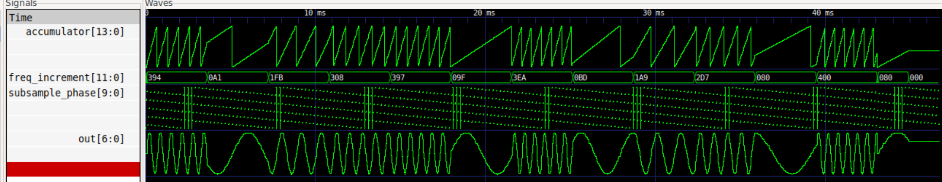
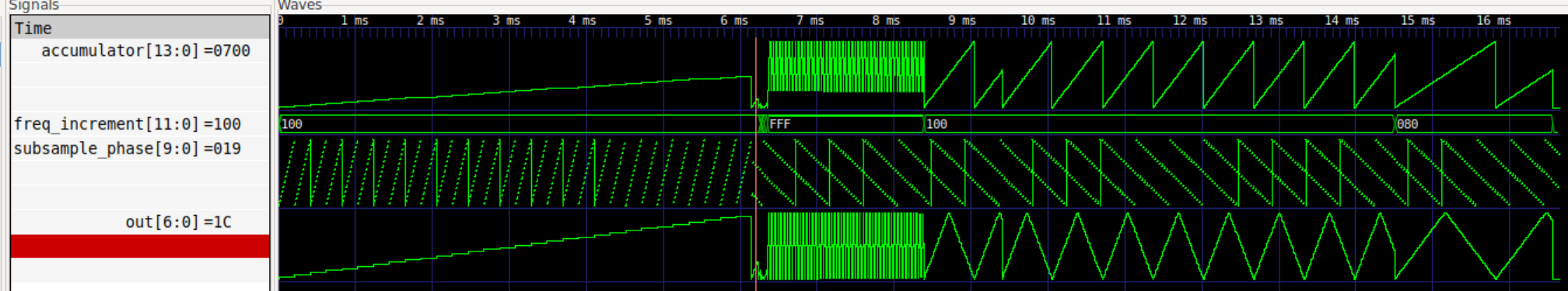
Sample test waveform for all tests in sine_test.py and triangle_test.py:
For each one, enter the directory and run make -B.
Expected Block-Level Test Results
These are the results when run, your values may vary slightly.
tb_pwm_phase
| Test | Status | Sim Time (ns) | Real Time (s) | Ratio (ns/s) |
|---|---|---|---|---|
| pwm_phase_test.test_reset_while_running | PASS | 18375.00 | 0.01 | 1392040.82 |
| pwm_phase_test.test_phase_counter_counts_and_wraps | PASS | 36575.00 | 0.03 | 1392378.31 |
| pwm_phase_test.test_pwm_duty_matches_sample_sum | PASS | 99365.00 | 0.08 | 1281090.80 |
| pwm_phase_test.test_pwm_sample_sum_overflow_edge | PASS | 54565.00 | 0.04 | 1299164.98 |
| pwm_phase_test.test_pwm_phase_threshold_behavior | PASS | 2303385.00 | 1.96 | 1173998.96 |
| TESTS=5 PASS=5 FAIL=0 SKIP=0 | 2512265.00 | 2.14 | 1174446.22 |
tb_regs
| Test | Status | Sim Time (ns) | Real Time (s) | Ratio (ns/s) |
|---|---|---|---|---|
| regs_test.test_regs_reset | PASS | 2450.00 | 0.00 | 1020157.75 |
| regs_test.test_regs_mid_transaction_reset | PASS | 665.00 | 0.00 | 1122872.93 |
| regs_test.test_regs_double_write | PASS | 3920.00 | 0.00 | 1284405.58 |
| regs_test.test_regs_timing | PASS | 17891720.00 | 11.35 | 1577041.76 |
| regs_test.test_regs_extreme_values | PASS | 11270.00 | 0.01 | 1362046.11 |
| regs_test.test_regs_error_states | PASS | 11200.00 | 0.01 | 768866.56 |
| regs_test.test_regs_large_addresses | PASS | 12180.00 | 0.01 | 1386302.32 |
| regs_test.test_regs_address_boundary_and_no_clobber | PASS | 5670.00 | 0.00 | 1395558.23 |
| TESTS=8 PASS=8 FAIL=0 SKIP=0 | 17939075.01 | 11.41 | 1572503.84 |
tb_sine
| Test | Status | Sim Time (ns) | Real Time (s) | Ratio (ns/s) |
|---|---|---|---|---|
| sine_test.test_sine_reset | PASS | 18200.00 | 0.02 | 1096046.30 |
| sine_test.test_random_frequencies | PASS | 43044400.00 | 35.99 | 1196040.83 |
| sine_test.test_silence | PASS | 3656240.00 | 3.05 | 1199115.46 |
| TESTS=3 PASS=3 FAIL=0 SKIP=0 | 46718840.00 | 39.07 | 1195669.64 |
tb_triangle
| Test | Status | Sim Time (ns) | Real Time (s) | Ratio (ns/s) |
|---|---|---|---|---|
| triangle_test.test_reset1 | PASS | 60.00 | 0.00 | 65214.42 |
| triangle_test.test_reset2 | PASS | 6148200.00 | 0.89 | 6927668.03 |
| triangle_test.test_midrun_reset_clears_wave | PASS | 123000.00 | 0.36 | 340395.99 |
| triangle_test.test_accumulator_increment | PASS | 170.00 | 0.00 | 272047.26 |
| triangle_test.test_frequency_control | PASS | 82020.00 | 0.24 | 338374.42 |
| triangle_test.test_max_freq_increment_overflow_behavior | PASS | 2037900.00 | 6.01 | 339309.66 |
| triangle_test.test_triangle_wave_shape | PASS | 1013900.00 | 3.06 | 331132.01 |
| triangle_test.test_full_range | PASS | 5109900.00 | 15.19 | 336412.01 |
| triangle_test.test_continuous_waveform | PASS | 2037900.00 | 6.20 | 328568.91 |
| triangle_test.test_zero_frequency | PASS | 102450.00 | 0.32 | 318233.89 |
| TESTS=10 PASS=10 FAIL=0 SKIP=0 | 16655500.01 | 32.30 | 515651.83 |
test.py
| Test | Status | Sim Time (ns) | Real Time (s) | Ratio (ns/s) |
|---|---|---|---|---|
| test.play_a_tune | PASS | 10001010.00 | 6.08 | 1646113.23 |
| test.single_sine_note | PASS | 3002100.00 | 1.89 | 1586899.63 |
| test.single_triangle_note | PASS | 3002100.00 | 1.83 | 1640564.33 |
| test.sine_and_triangle_together | PASS | 3002100.00 | 1.82 | 1653389.06 |
| TESTS=4 PASS=4 FAIL=0 SKIP=0 | 19007310.00 | 11.63 | 1634247.66 |
Audio Test
This test runs a really long (around 1s sim time) RTL simulation, exports the data, then simulates the PWM signal being filtered by the Audio Pmod circuit to generate a .wav file that you can listen to!
cd test/ && make -B AUDIO=yes- this takes 10 minutes on my machine, will vary depending on hardware. It generates three tones of 0.3s each. This will createpwm_edges.login thetest/directory.cd ../pmod-sim/and run the KiCad ngspice simulation of the Pmod circuit to export the frequency response, or use the pre-simulatedfreq_response.csv.- run
filter_pwm.py, which will apply the filter to thepwm_edges.logfile and createoutput.wav.
Hardening & Viewing
See: https://tinytapeout.com/guides/local-hardening/
External hardware
Audio Pmod required: Audio-Pmod-p716541601
Project Duties & Acknowledgements
Evan Li:
sine.vregister_interface.vphase_counter.vaudio_chip.vpwm.v/tb_regssub-block tests/tb_sinesub-block tests- Audio test -
audio_test.py,audio_util.py - pmod simulation -
/pmod-sim - Integration tests -
test.py
Rongbin Gu:
triangle.vsync.vaudio_chip.vpwm.v/tb_pwm_phasesub-block tests/tb_regssub-block tests/tb_trianglesub-block tests- Integration tests -
test.py
IO
| # | Input | Output | Bidirectional |
|---|---|---|---|
| 0 | ADDR0 | REG_IN0 | |
| 1 | ADDR1 | REG_IN1 | |
| 2 | ADDR2 | REG_IN2 | |
| 3 | ADDR3 | REG_IN3 | |
| 4 | WRITE_PHASE | REG_IN4 | |
| 5 | WRITE_EN | REG_IN5 | |
| 6 | REG_IN6 | ||
| 7 | PWM_OUT | REG_IN7 |