482 LDO Regulator Skywater 130nm
482 : LDO Regulator Skywater 130nm
- Author: Engineer of CTW
- Description: Low Drop Out Regulator with Supply Independent Current Circuit
- GitHub repository
- Open in 3D viewer
- Clock: 0 Hz
HOW IT WORKS
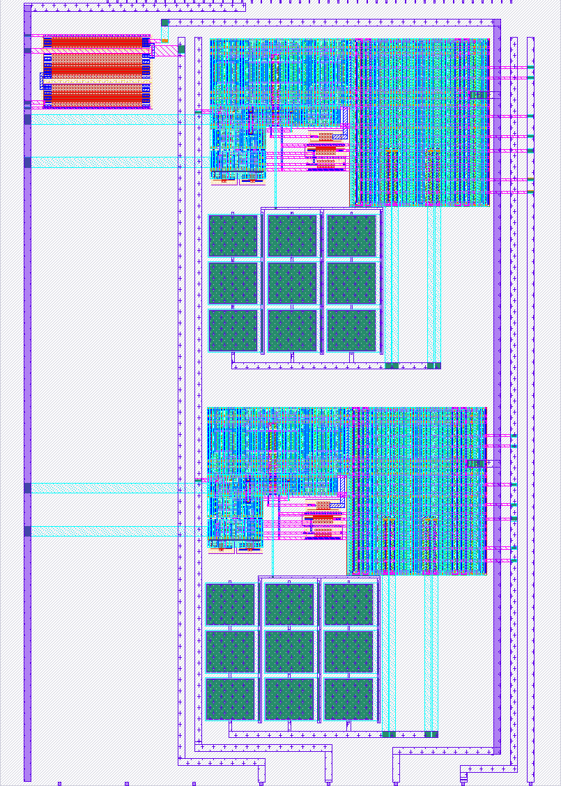
This project is an analog Low Dropout Regulator designed using the SkyWater 130 nm Process Design Kit.
The LDO Version 2 architecture contains five main functional blocks:
-
Current Generator The Current Generator provides the internal bias current and bias voltage required by the analog core.
-
Error Amplifier The Error Amplifier uses an Operational Transconductance Amplifier to compare the feedback voltage with the reference voltage. Its output controls the pass device.
-
Push-Pull Composite Power Transistor The Push-Pull Composite Power Transistor works as the main pass device. It supplies current to the load while keeping the output voltage regulated.
-
Feedback Network The Feedback Network senses the output voltage and sends a scaled feedback voltage back to the Error Amplifier.
-
Load Circuit The Load Circuit represents the output load condition used during simulation.
The regulator targets an output voltage of approximately 1.3 V from a nominal input supply of 1.5 V. The supported load current range is from 0 A to 10 mA.
Main pre-layout simulation results at nominal TT corner, 1.5 V, and 27 °C:
Quiescent current: approximately 19 µA to 73.66 µA, depending on load current. Dropout voltage: approximately 187.8 mV to 212.2 mV. On-chip capacitance: approximately 3.11 pF. Load capacitor range used in simulation: 0 pF to 100 pF. Maximum load current: 10 mA. Load regulation: approximately 2.45 mV/mA.
Line regulation from 1.6 V to 2.0 V: Nearly no load: 5.6127 mV/V. Light load, around 10 µA: 3.2926 mV/V. Maximum load, around 10 mA: 1.0640 mV/V.
HOW TO TEST
To verify the LDO regulator operation, the following tests can be performed.
- Basic Operation Test
Apply a nominal input voltage of 1.5 V to the input supply pin.
Expected result: The output voltage should be regulated at approximately 1.3 V. The quiescent current should be in the expected range of approximately 19 µA to 73.66 µA, depending on the load condition. The circuit should remain stable under the selected load condition.
- Load Regulation Test
Sweep the load current from 0 A to 10 mA.
Use load capacitance values from 0 pF to 100 pF, matching the simulation condition.
Expected result: The output voltage should remain close to the nominal regulated value. The expected load regulation is approximately 2.45 mV/mA.
- Line Regulation Test
Sweep the input voltage from 1.6 V to 2.0 V.
Measure the change in output voltage and calculate line regulation using:
Line Regulation = Delta Vout / Delta Vin
Expected pre-layout results: Nearly no load: approximately 5.6127 mV/V. Light load, around 10 µA: approximately 3.2926 mV/V. Maximum load, around 10 mA: approximately 1.0640 mV/V.
- Startup Test
Apply the input supply with a 1 µs switching edge and observe the output startup waveform.
Expected nominal startup behavior: Settling time is approximately 30 µs to 35 µs under minimum-load startup conditions. Startup overshoot is approximately 64.5 mV to 77.5 mV, depending on capacitance condition.
- Load Transient Test
Apply a load transient up to the maximum load condition.
Expected pre-layout results at maximum load:
Undershoot: Max-cap condition: approximately 306.4 mV, settling in about 20 µs. Min-cap condition: approximately 426.9 mV, settling in about 30 µs.
Overshoot: Max-cap condition: approximately 172.6 mV, settling in about 10 µs. Min-cap condition: approximately 182.6 mV, settling in about 5 µs.
- Power Supply Rejection Ratio Test
Run an AC simulation to measure Power Supply Rejection Ratio.
Expected Power Supply Rejection Ratio result under max-cap and minimum-load condition: At 1 Hz: approximately -31.22 dB. At 1 kHz: approximately -31.06 dB. At 10 kHz: approximately -24.39 dB. At 100 kHz: approximately -6.47 dB.
- Open-Loop Response Test
Break the feedback loop using the proper small-signal loop-gain testbench and run AC analysis.
Expected open-loop response under max-cap and minimum-load condition: DC loop gain: approximately 25.18 dB. Bandwidth: approximately 8.67 kHz. Unity-Gain Frequency: approximately 142 kHz. Phase Margin: approximately 53.16 degrees.
EXTERNAL HARDWARE
For silicon or board-level validation, the following equipment is recommended:
Stable DC power supply for the LDO input supply. Programmable DC electronic load or variable load circuit capable of sinking up to 10 mA. Small load capacitors in the pF range for matching the simulated load-capacitance conditions. Oscilloscope for startup, line transient, and load transient measurements. Digital multimeter for DC output voltage, dropout voltage, and current measurement. Source-measure unit, if available, for accurate low-current and dropout characterization.
NOTES
The values listed above are based on pre-layout simulation results for LDO Version 2.
Post-layout parasitic extraction may change the final performance, especially transient response, loop stability, Power Supply Rejection Ratio, and dropout behavior.
The simulated load capacitor range is 0 pF to 100 pF, not 0 µF to 100 µF.
IO
| # | Input | Output | Bidirectional |
|---|---|---|---|
| 0 | nc | ||
| 1 | |||
| 2 | |||
| 3 | |||
| 4 | |||
| 5 | |||
| 6 | |||
| 7 |
Analog pins
ua | PCB Pin | Internal index | Description |
|---|---|---|---|
| 0 | A0 | 0 | OUT3 |
| 1 | A4 | 4 | OUT2 |
| 2 | A1 | 1 | VDD |
| 3 | A3 | 3 | Vref |
| 4 | A2 | 2 | OUT1 |