256 Array Multiplier
256 : Array Multiplier

- Author: Jeryl Ho & Justin Park
- Description: 4x4 Structural Array Multiplier
- GitHub repository
- Open in 3D viewer
- Clock: 0 Hz
How it works
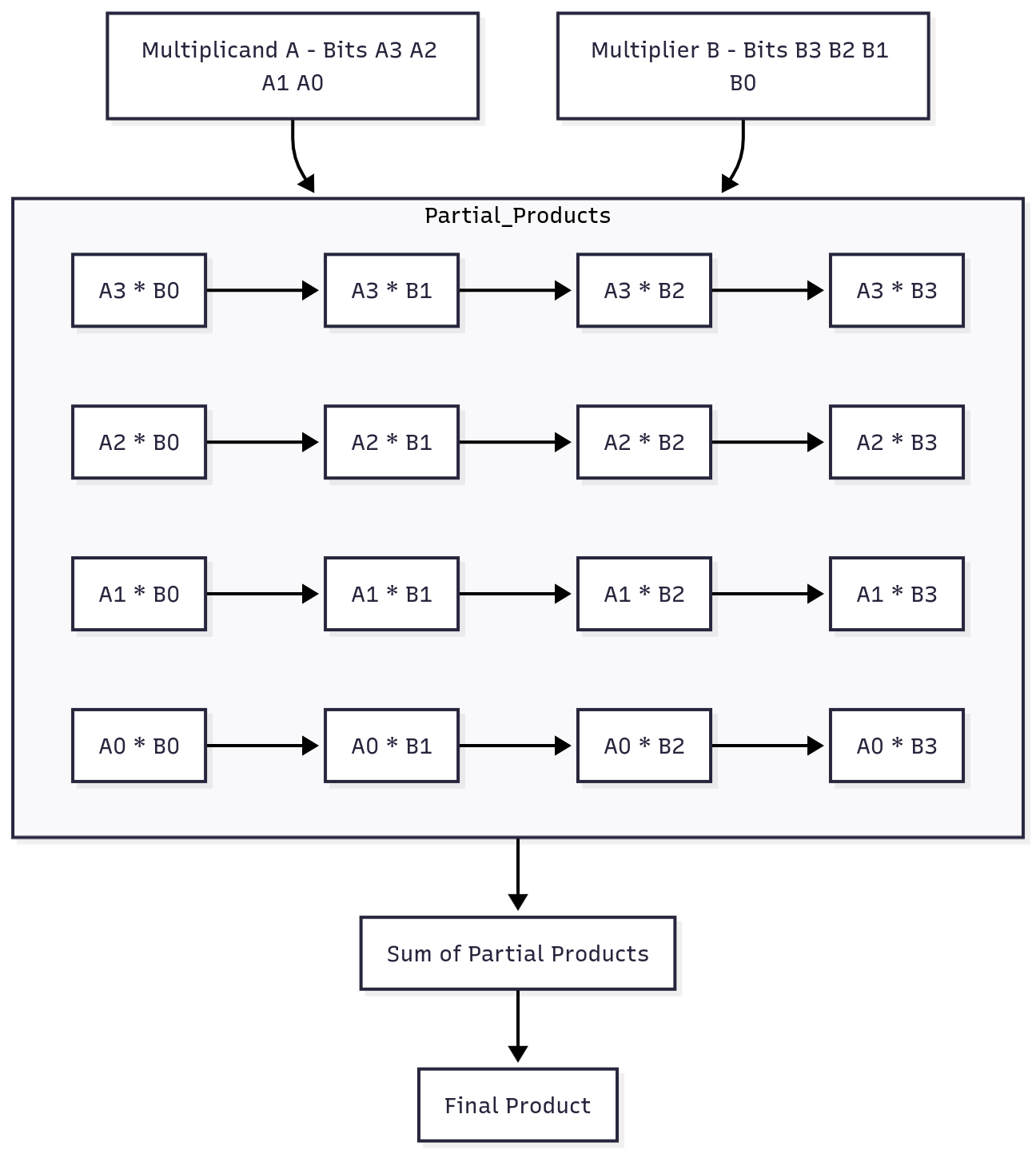
An array multiplier is a combinational circuit that performs binary multiplication by generating and summing partial products. Here’s how a 4x4 array multiplier operates:
-
Binary Multiplicand and Multiplier: A 4x4 multiplier takes two 4-bit binary numbers (e.g., ( A = A_3 A_2 A_1 A_0 ) and ( B = B_3 B_2 B_1 B_0 )) as inputs. Each bit in ( A ) is multiplied by each bit in ( B ), creating 16 partial products.
-
Partial Product Generation: Each bit in ( A ) is ANDed with each bit in ( B ), forming a matrix of partial products. For instance, if ( A = 1011 ) and ( B = 1101 ), then ( A_3 \times B_3 ), ( A_3 \times B_2 ), and so forth are calculated.
-
Shifting and Summing: Each row of partial products corresponds to a shifted version based on the position of the bits in ( B ). For example, the row generated by ( A_3 ) will be shifted three places to the left.
-
Adding Partial Products: The shifted partial products are summed column by column, similar to traditional addition in binary, often using full adders or half adders.
-
Final Product: The result is an 8-bit product that represents the multiplication of the two 4-bit inputs.
 {height=45%}
How to test
To test the array multiplier:
- Set up the multiplier by providing binary inputs for both the multiplicand (A) and the multiplier (B).
- Run the simulation or test in hardware to verify that each partial product is calculated correctly.
- Ensure that the partial products are properly shifted and summed to produce the final product.
- Compare the final output with the expected result from standard binary multiplication to confirm accuracy.
IO
| # | Input | Output | Bidirectional |
|---|---|---|---|
| 0 | q[0] | p[0] | |
| 1 | q[1] | p[1] | |
| 2 | q[2] | p[2] | |
| 3 | q[3] | p[3] | |
| 4 | m[0] | p[4] | |
| 5 | m[1] | p[5] | |
| 6 | m[2] | p[6] | |
| 7 | m[3] | p[7] |