431 Enigma - 52-bit Key Length
431 : Enigma - 52-bit Key Length
- Author: Virantha Ekanayake
- Description: Silicon implementation of an Enigma I machine with a limited plugboard supporting 3 wires
- GitHub repository
- Open in 3D viewer
- Clock: 0 Hz
How it works
Background
This project features a silicon implementation of a 52-bit equivalent key model of the WWII-era Enigma code machine used by the Germans. The British, led by Alan Turing (as depicted in The Imitation Game), cracked this code, giving the Allies a crucial advantage in the war.
This electronic version is accurate and will match any simulator you can find on the web^1. Although almost every Enigma operates on similar principles, the particular model implemented here is the Enigma I^3 used by the German Army and Air Force; it comes with 3 rotor slots, the 5 original Rotors, the UKW-B Reflector, and plugboard. The only limitation is that the plugboard only supports 3 wires, whereas the actual wartime procedure was to use up to 10 wires. This limits the key length of this implementation to 52-bits. The calculation is shown below.
Key-length Calculation
The Enigma is a symmetric^4 encryption engine, and the equivalent key length is comprised of the different settings and ways the rotors and plugboard can be arranged. See the excellent analysis^5 from Dr. Ray Miller at NSA for more details on the calculations below:
- Selecting the three rotors, which can be arranged from right to left in any order:
5 x 4 x 3 = 60 possible ways
- Starting position of each rotor:
26 * 26 * 26 = 17576
- Ring of each rotor (only two right rotors matter):
26*26 = 676
- Plugboard with 3 wires (see table on p.9 for p=3^3):
= 26! / (26-6)! / 3! / 8 = 3,453,450 ways to plug in 3 wires
The total ways (# of keys) to set up this particular Enigma is therefore:
60 * 17576 * 676 * 3,453,450 = 2,461,904,276,832,000 ways
yielding a key length of ~52-bits.
Implementation
Using the Python-based hardware description tool Amaranth HDL^7 for the first time made building, testing, and generating the Verilog implementation much easier. Given the complexity of the rotors’ input-output mappings, I would’ve needed to write Python scripts anyway to generate Verilog logic. Amaranth streamlined this process and allowed seamless integration with my reference Python implementation for test generation.
- Rotor design:
- Meeting the tight area requirements involved several design iterations that narrowly missed targets late in the cycle. Amaranth’s flexibility made re-architecting much simpler. For example, my initial approach of implementing three separate combinational hardware rotors was too large and lacked configurability. I ultimately created a single reconfigurable rotor block that processes data over six cycles, effectively forming a six-rotor pipeline (three forward, three backward after reflection).
- Plugboard Design:
-
Initial Attempt: A 26-entry, 5-bit lookup table using DFFs, which proved too large.
-
Next Approach: A scan-chain-based design, but the hold-fix buffers and comparison logic made it even larger.
-
Final Solution: A 26-entry, 5-bit lookup table using Skywater 130 standard-cell latches. This worked well since the plugboard functions like a ROM, with only a few initial writes to set the configuration. These writes are precisely pulsed using the state machine.
-
| Key statistics | |
|---|---|
| Utilization | 81% |
| Cells | 1583 |
| DFF | 67 |
| Latches | 130 |
| Frequency | 35MHz |
Operation
The Enigma is designed to accept an 8-bit input (command plus data) at the clk edge. The internal state machine then takes a varying number of clk cycles to respond, raising the "Ready" signal when it's ready to accept the next command. If the command generates an output, the raw value will be output on the bidir pins, and the LCD display will show the character generated.
Pinouts
| Description | Width | Direction | Signal(s) |
|---|---|---|---|
| Command | 3 | in | ui_in[7:5] |
| Data | 5 | in | ui_in[4:0] |
| Scrambled output char | 5 | out | uio_out[4:0] |
| Ready | 1 | out | uio_out[5] |
| 7-segment LCD | 7 | out | uo_out[6:0] |
Commands
The machine accepts the following 8 commands:
| Encoding[^6] | Command | Data | Description |
|---|---|---|---|
| 000 | NOP | N/A | Do nothing |
| 001 | LOAD_START | Setting 0-25 (A-Z) | Set the start position of a rotor. Do this three times in succession to set each of the three rotors (right to left) |
| 010 | LOAD_RING | Setting 0-25 (A-Z) | Set the ring setting of a rotor. Do this three times in succession to set each of the three rotors (right to left) |
| 011 | RESET | N/A | Go back to the initial state |
| 100 | SCRAMBLE | Input char 0-25 (A-Z) | Run a letter through the rotor. The Ready signal will be asserted when the scrambled character is output |
| 101 | LOAD_PLUG_ADDR | Src 0-25 (A-Z) | Set an internal register to where the start of the plug should go. This command should be followed by LOAD_PLUG_DATA to set the destination |
| 110 | LOAD_PLUG_DATA | Dst 0-25 (A-Z) | Set the other end of the plug. Note that this connection is unidirectional, so if you want A,B connected, then you need to do two sequences of these commands to first set A->B and then B->A |
| 111 | SET_ROTORS | Rotor 0-4 | Pick the Rotor type for each slot where Rotor I=0, Rotor II=1, ... Rotor V=4. Do this three times in succession to pick each of the rotors (right to left). Default is Rotor I, II, III from right to left, where Rotor I is closest to the plugboard |
Sample run
At some point, I'll have some code ready for running on the RPi on the PC, but for now, here is the pseudo code for setting up and scrambling/descrambling with this machine:
    # Install the rotors
    send_command(SET_ROTORS, 0)   # Set slot 0 to Rotor I
    send_command(SET_ROTORS, 1)   # Set slot 0 to Rotor II
    send_command(SET_ROTORS, 2)   # Set slot 0 to Rotor III

    # Dial start position of the rotors
    send_command(LOAD_START, 15)  # Set rotor 0 start position to P
    send_command(LOAD_START, 5)   # Set rotor 1 start position to F
    send_command(LOAD_START, 1)   # Set rotor 2 start position to B

    # Dial ring position of the rotors
    send_command(LOAD_RING, 18)  # Set rotor 0 start position to S
    send_command(LOAD_RING, 5)   # Set rotor 1 start position to F
    send_command(LOAD_RING, 24)  # Set rotor 2 start position to Y

    # Set up the plugboard
    # First, configure the plugboard default configuration with
    # no swizzling of letters
    for i in range(26):
        send_command(LOAD_PLUG_ADDR, i)
        send_command(LOAD_PLUG_DATA, i)

    # Now, plug in three wires
    send_command(LOAD_PLUG_ADDR, 0)    # connect A -> N
    send_command(LOAD_PLUG_DATA, 13)

    send_command(LOAD_PLUG_ADDR, 13)   # connect N -> A
    send_command(LOAD_PLUG_DATA, 0)

    send_command(LOAD_PLUG_ADDR, 3)    # connect D -> E
    send_command(LOAD_PLUG_DATA, 4)

    send_command(LOAD_PLUG_ADDR, 4)   # connect E -> D
    send_command(LOAD_PLUG_DATA, 3)

    send_command(LOAD_PLUG_ADDR, 25)    # connect Z -> B
    send_command(LOAD_PLUG_DATA, 1)

    send_command(LOAD_PLUG_ADDR, 1)   # connect D -> Z
    send_command(LOAD_PLUG_DATA, 25)

    # Now, enter letters into the machine and watch the coded char
    # appear on the display
    send_command(SCRAMBLE, 11)  # 'L' -> 'X'
    send_command(SCRAMBLE, 14)  # 'O' -> 'K'
    .
    .
    .
[^6]: See the src/defines.py file
Control FSM
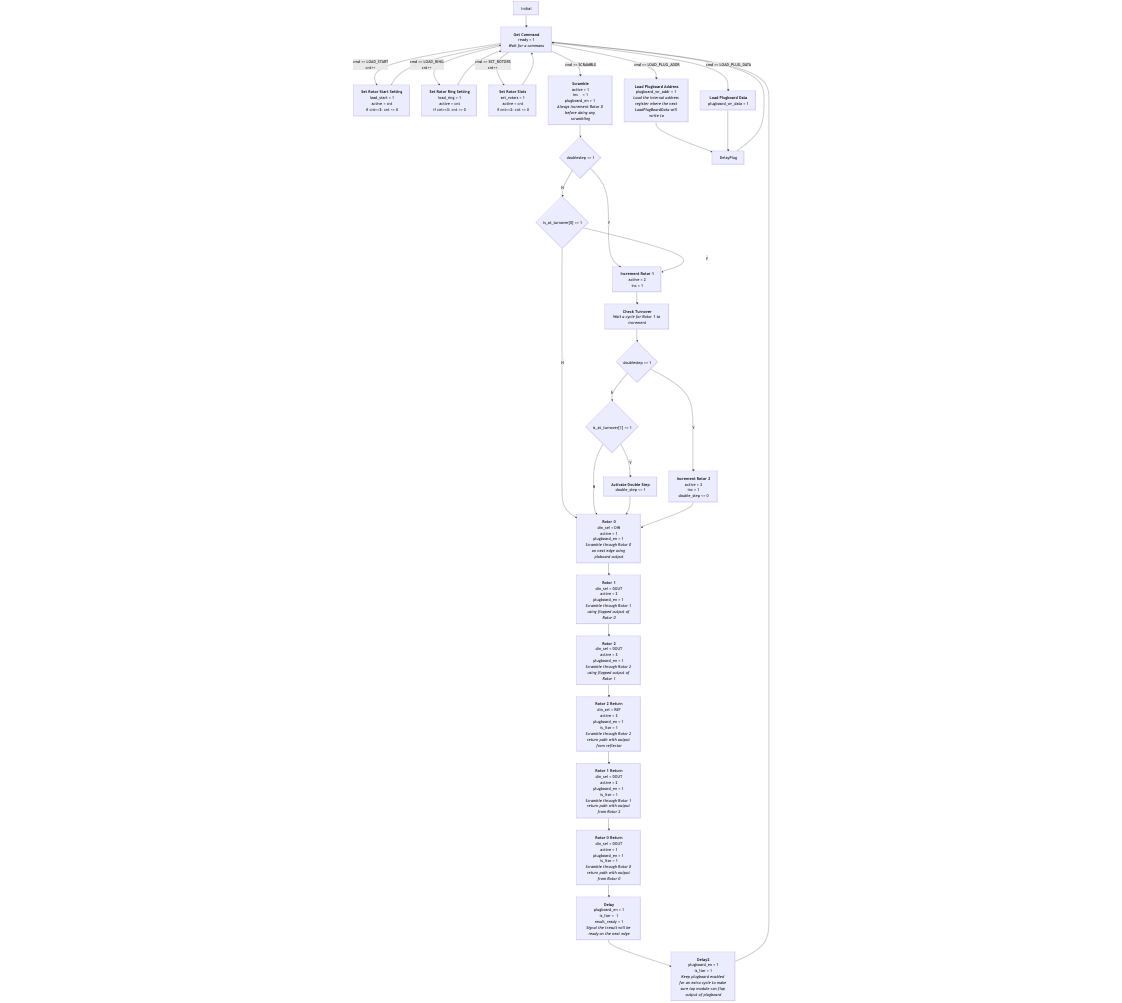
The state machine diagram source can be found on github^8.
How to test
Design verification
-
Generate the verilog from the Amarangth HDL source
 cd tt10-enigma
 python -m src.top
This will write a file
src/am_top.vwith the Enigma block. This block is connected to the TinyTapeout harness usingsrc/project.v -
Run the functional test
cd test make -
Run the gate-level tests: After hardening (synthesis/pnr/gds), copy the gate_level_netlist.v into the test/ directory. Then:
make -B GATES=yes
External hardware
None. Uses the built-in 7-segment display on the PCB.
IO
| # | Input | Output | Bidirectional |
|---|---|---|---|
| 0 | din[0] | seg[0] | dout[0] |
| 1 | din[1] | seg[1] | dout[1] |
| 2 | din[2] | seg[2] | dout[3] |
| 3 | din[3] | seg[3] | dout[4] |
| 4 | din[4] | seg[4] | dout[5] |
| 5 | cmd[0] | seg[5] | ready |
| 6 | cmd[1] | seg[6] | |
| 7 | cmd[2] | GND |