164 Delay Line
164 : Delay Line
- Author: Ashley J. Robinson
- Description: A simple delay line with instrumentation
- GitHub repository
- Open in 3D viewer
- Clock: 50000000 Hz
How it works
-
A delay line output changes based on time delay of different variables such as process, voltage and temperature.
-
There are may different delay line architectures.
- https://springerplus.springeropen.com/articles/10.1186/s40064-016-2090-z.
-
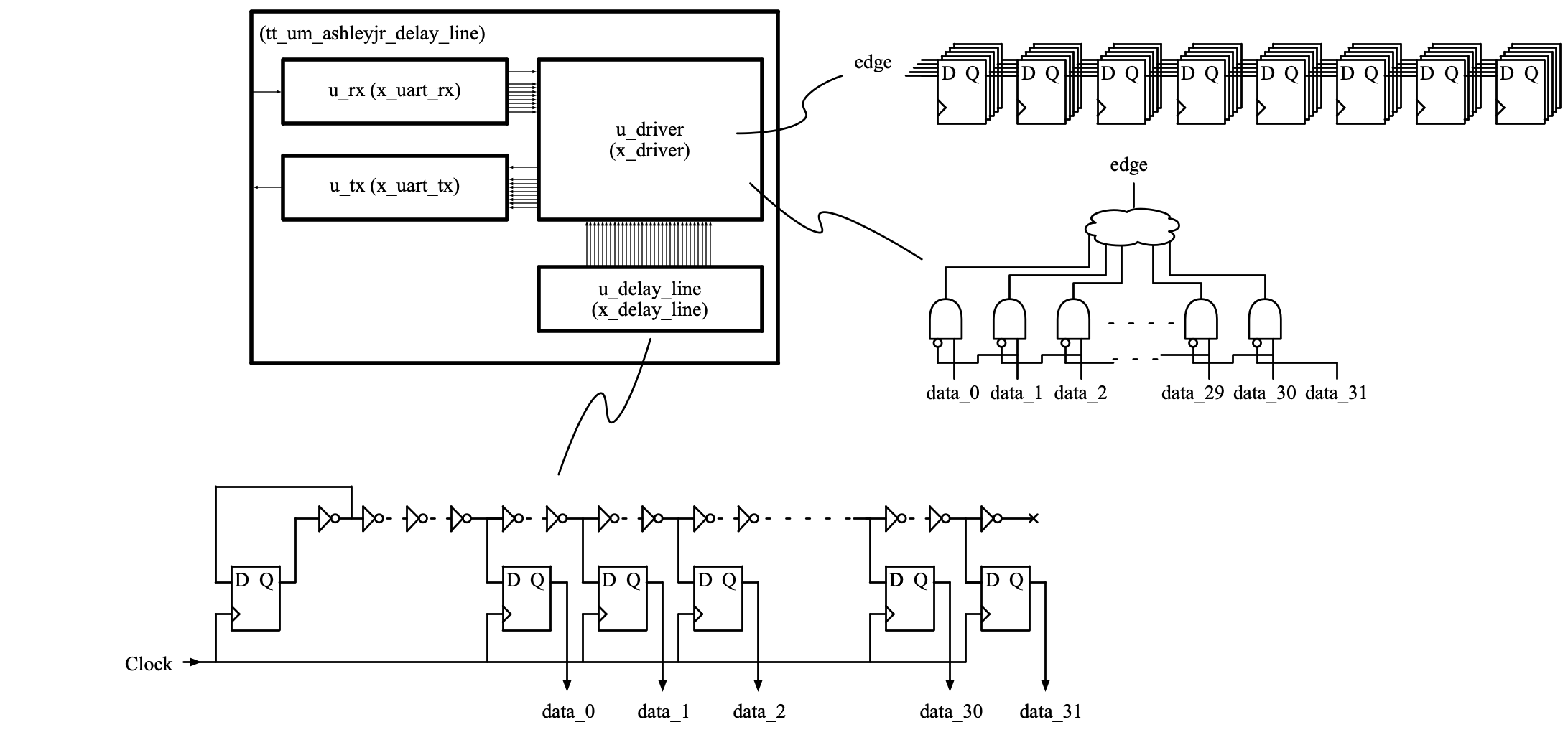
This implementation is a simple tapped delay line.
-
The continually changing data races through a chain of inverters.
-
The chain is sampled at different stages to become a digital signal.
-
An edge detection circuit is used find the rising which is then converted in a binary value.
-
A bank of flops is used to sample 8 sequential rising edge values.
How to test
-
https://github.com/ashleyjr/tt04-delay-line/blob/main/src/test/silicon_test.py
-
This python script uses pyserial to run a set of tests on the design
-
python3 silicon_test.py --help
-
-
UART
-
The UART is the only interface to the design
-
9600 baud
-
Least significant bit first
-
1 Start bit
-
8 Data bits
-
No parity bit
-
1 Stop bit
-
Taken from https://github.com/ashleyjr/rtl-uart
-
-
The bottom 4 bits [3:0] of the UART frame make up the command
-
4'h0: Shift In
-
Shift the top 4 bits [7:4] of the frame in to memory
-
The memory is shifted 4 places to the left
-
The data is placed in to the bottom 4 bits [3:0]
-
This command is to test the silicon and debug software
-
-
4'h1: Shift Out
-
Shift the top 8 bits [39:32] of memory out to UART Tx
-
The memory is shifted 8 places to the left
-
-
4'h2: Full Sample
-
Take a full 32-bit sample from the delay line and place in memory
-
The sample is placed in to the bottom 32 bits [31:0]
-
The shift out command may be used to read the sample
-
-
4'h3: Scope
-
Take 8 samples from the delay line at a 25MHz sample rate
-
These sample use the edge detection logic to find the position of the rising edge
-
These samples are 5 bits wide
-
The samples are shifted in to the memory
- Sample 0: [39:35]
- Sample 1: [34:30]
- Sample 2: [29:25]
- Sample 3: [24:20]
- Sample 4: [19:15]
- Sample 5: [14:10]
- Sample 6: [9:5]
- Sample 7: [4:0]
-
The shift out command may be used to read the sample
-
-
4'h4 to 4'hF inclusive
- Ignored
-
External hardware
FTDI Cable
IO
| # | Input | Output | Bidirectional |
|---|---|---|---|
| 0 | UART Rx | UART Tx | Tied Low |
| 1 | Tied Low | Tied Low | |
| 2 | Tied Low | Tied Low | |
| 3 | Tied Low | Tied Low | |
| 4 | Tied Low | Tied Low | |
| 5 | Tied Low | Tied Low | |
| 6 | Tied Low | Tied Low | |
| 7 | Tied Low | Tied Low |