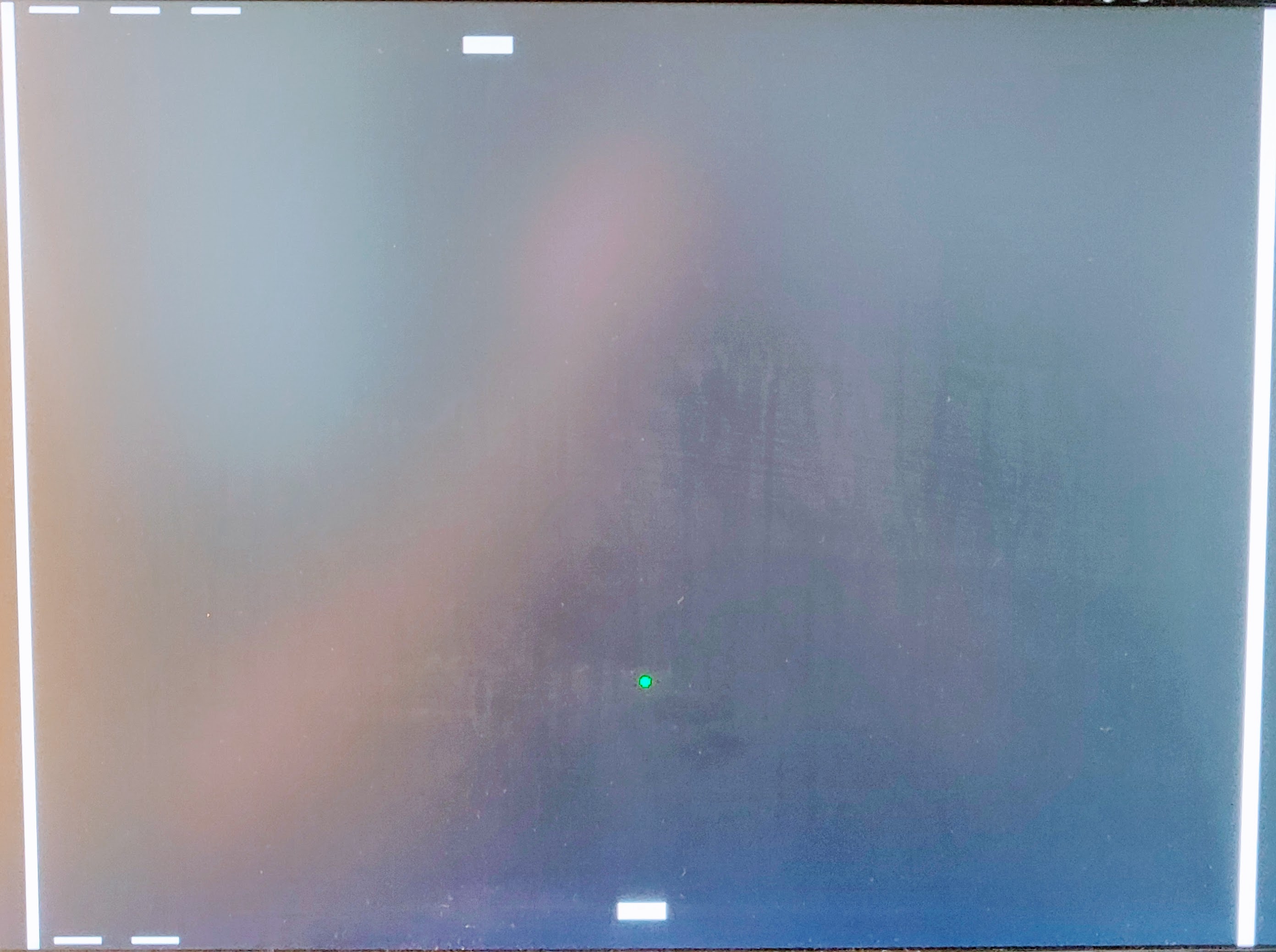
178 Pong
178 : Pong

- Author: Robbert-Jan de Jager
- Description: This is a small pong game implemented in HDL. It uses a VGA connector to output the video signal. The game is controlled with 3 buttons per player. The left button moves the paddle to the left, the right button moves the paddle to the right and the action button starts the game. The game is over when one player is out of lives.
- GitHub repository
- Open in 3D viewer
- Clock: 25175000 Hz
- Feedback: ✅ 1
How it works
Basic operation
The core of the design is the vga_timing module. This module generates all the required timing signals. Some of these signals like hsync and vsync are used to generate the video signal, while others like the horizontal and vertical position are used to generate the graphics. The horizontal and vertical sync signals are also used for the game logic.
Before outputting the video signal the video mux selects the correct input color to display. It does so based on the highest priority component that wants to output a color.
We have multiple painter modules. These generate from the current game state and the current horizontal and vertical position the correct color to display. Ideally the painters would not contribute to the game logic, but for optimization reasons they do.
While drawing a frame the game logic keeps track of collisions. It does so by checking if multiple painters want to draw at the same position. If so it will latch a collision, which will be processed after drawing the frame.
At the end of each frame the game logic will calculate the next ball position, taking collisions into account. The collision with the paddle is special. To have an entertaining game that does not play the same every time the ball will bounce off the paddle at a different angle depending on where it hits. This is done by splitting the paddle into multiple segments and checking for collisions with these segments. The game logic will look at the segment when a paddle collision was registered. An exception to the end of frame gamestate update is the breaking of blocks. It would require too much memory to keep the updated state for the next frame. Instead we will update the row of blocks that was just finished drawing.
How to test
This is a small breakout game implemented in HDL. It uses a VGA connector to output the video signal. The game is controlled with 3 buttons per player. The left button moves the paddle to the left, the right button moves the paddle to the right and the action button starts the game. The game is over when all blocks are destroyed or when the ball hits the bottom of the screen.
Required hardware
This project requires a VGA monitor and a VGA DAC. An easy way to create the VGA DAC is to use 3 2-bit R2R DACs. The 2-bit R2R DACs can be created using 2 resistors per bit. The resistors should be 200Ohm and 390Ohm. For the 3.3V power supply.
What has not been verified is the current sourcing capability of the ASIC, If it can not at least source 10mA through each pin and 30mA through the power supply pins you should add a buffer before the DAC.
The VGA DAC should be connected as follows:
           ___       ___
Bit 0 ----|___|--+--|___|-- GND
           390   |   390
                .-.
                | |
            200 | |
                '-'
          ____   |
Bit 1 ---|____|--+---- Out
          390
Every color should have an identical copy of this DAC. The red DAC should be connected to the red VGA pin, the green DAC to the green VGA pin and the blue DAC to the blue VGA pin. The outputs of the DACs should be connected to the VGA connector. The HSync and VSync pins should also be connected to the VGA connector. The following connections need to be made to the VGA connector:
- Red DAC output to VGA connector pin 1
- Green DAC output to VGA connector pin 2
- Blue DAC output to VGA connector pin 3
- HSync to VGA connector pin 13
- VSync to VGA connector pin 14
- GND to VGA connector pin 5, 6, 7, 8
Board configuration
The ASIC requires an input clock of 25.175MHz. The 7-Segment display is not used.
External hardware
3x 2bit DAC for the red, green and blue video signals. VGA connector. 3 buttons.

IO
| # | Input | Output | Bidirectional |
|---|---|---|---|
| 0 | HSync | ||
| 1 | VSync | HBlank | |
| 2 | Button P2 left | Red output bit 0 | VBlank |
| 3 | Button P2 right | Red output bit 1 | sound output. Connect to a speaker with amplifier. |
| 4 | Button P2 action | Green output bit 0 | |
| 5 | Button P1 left | Green output bit 1 | |
| 6 | Button P1 right | Blue output bit 0 | |
| 7 | Button P1 action | Blue output bit 1 |
User feedback
- robojan👑: