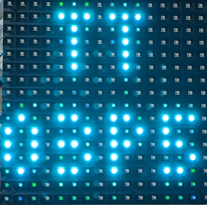
112 LED Panel Driver
112 : LED Panel Driver
- Author: Tom Keddie
- Description: Drives a 16x16 P10 LED panel
- GitHub repository
- Clock: 12000000 Hz
How it works
- The circuit updates a P10 16x16 LED display module
- It initially displays the string TT03P5
- It provides a 1.2Mbaud uart input to
- paint pixels
- erase pixels
- clear the display
- change the displayed colour
- Functionality is limited by resource availability
- single colour at once
- no double buffer, updates may have artifacts
- Mode pin to allow for 2 different clocking patterns
How to test
- Connect the display module as per the outputs
- Connect the uart
- Power on and see the TT03P5 text
- If the display is swapped by quadrant change the mode pin
- Use the script(s) in the software directory to control the display
External hardware
led panel, level converter to 5V logic

IO
| # | Input | Output | Bidirectional |
|---|---|---|---|
| 0 | uart | red0 | red1 |
| 1 | mode | blue0 | blue1 |
| 2 | b | green1 | |
| 3 | blank | ||
| 4 | green0 | ||
| 5 | a | ||
| 6 | clk | ||
| 7 | latch |