453 tt08-octal-alu
453 : tt08-octal-alu

- Author: Theo Kachelski
- Description: Executes binary operations on two octal numbers encoded in an 8-bit instruction and outputs the result to the 7-segment display.
- GitHub repository
- Open in 3D viewer
- View in Wokwi
- Clock: 0 Hz
How it works
This design executes binary operations on two octal numbers encoded in an 8-bit instruction and outputs the result to the 7-segment display. The instruction is made up of 8 total bits.
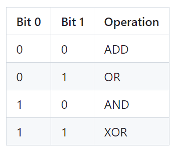
Bits 0 and 1 make up the operation code. Operations are according to the following table.

Bits 2, 3, and 4 make up operand A. Bit 2 is MSB and bit 4 is LSB.
Bits 5, 6, and 7 make up operand B. Bit 5 is MSB and bit 7 is LSB.
A full operation would be decoded like this

How to test
-
Craft a instruction following the above decoding table.
-
Enter the instruction on the TT08 PCB's input pin dip switches.
-
View the result on the 7 segment display
Note: An overflow condition during an add operation will illumniate the 7 segment display's DP.
Examples:
-
0 0 1 0 0 0 0 1 -> ADD 4, 1 -> Displays 5 on 7-Segment Display
-
1 1 1 0 0 1 0 1 -> XOR 4, 5 -> Displays 1 on 7-Segment Display
-
1 0 1 0 0 1 0 1 -> AND 4, 5 -> Displays 4 on 7-Segment Display
-
0 1 1 1 0 1 0 1 -> OR 6, 5 -> Displays 7 on 7-Segment Display
-
0 0 1 0 1 1 1 0 -> ADD 5, 6 -> 7-Segment Display DP illuminated indicating overflow condition
External hardware
The only external hardware required is the 7 segment display provided by the tt08 PCB.
IO
| # | Input | Output | Bidirectional |
|---|---|---|---|
| 0 | Operation bit 1 | Segment A | |
| 1 | Operation bit 2 | Segment B | |
| 2 | Operand A bit 1 (MSB) | Segment C | |
| 3 | Operand A bit 2 | Segment D | |
| 4 | Operand A bit 3 (LSB) | Segment E | |
| 5 | Operand B bit 1 (MSB) | Segment F | |
| 6 | Operand B bit 2 | Segment G | |
| 7 | Operand B bit 3 (LSB) | Segment DP |