528 float_synth
528 : float_synth
- Author: Niklaus Leuenberger
- Description: Synthesizing the VHDL-2008 IEEE.float_pkg
- GitHub repository
- Open in 3D viewer
- Clock: 50000000 Hz
How it works
This project came about with the simple question: Can we write lazy HDL and let the tools optimize our sloppiness?
Spoiler: We absolutely can!
The Idea: Retiming
It is very easy to write combinational logic. Ignore the clock, just simply do everything at once, use deep MUX trees, if else if if else else if and so on. But that has a cost. The result will have a very long critical path and timing closure will be almost impossible. Sure at clock frequencies of a few kHz this is an non-issue. But try to target anything faster and your design will not reach timing closure.
Registers to the rescue! We could, like its usually done, partition the design in logical steps and add flip-flops inbetween to effectively pipeline the design. Thats everything but easy. Whole new HDL languages have came to be just because this is not easy. See PipelineC for example.
But we are lazy and want to test what the tools can do about it. So we simply add, after our lazy design, a few (or many) flip-flops back-to-back like a shift register. That does not change what is computed, but simply introduces latency, i.e. the output is delayed by N clocks. The excellent ABC tool from Alan Mishchenko, which is mostly integrated into Yosys, then does the heavy lifting and retimes the flip-flops to wherever it results in the minimal delay.

Retiming is the process of moving flip-flops over combinational logic. As a very contrived example consider the above tree of AND gates. At its output there are two flip-flops. We can retime one of the FFs backwards by moving it over the last AND gate and duplicate it for each input. This does not change the behavour to the outside world.

In the retimed design, we now only have a single AND gate in the combinational path from one FF to the other. The original had two. Less logic depth equals a faster possible clock. But of course, there is a drawback. There always is. Instead of only 2 FFs, we now have 3. This means more area, which in ASICs is not free. So YMMV.
Note that there are other types of retiming. Here we discussed retiming for minimal delay. ABC can also retime for minimal area. For the above example this would be the reverse. Merge the FF from the AND gates inputs to a single FF at the output. Usually you want a healthy balance of delay and area. But this is ... complicated.
The Usecase: IEEE.float_pkg
Since VHDL-2008, the VHDL IEEE library has contained the excellent float_pkg (as well as fixed_pkg) from David Bishop. It describes on a high and generic level how a floating point number works and provides procedures for every mathematical operation.
With it, a fully IEEE compliant floating point multiplier is as simple as:
y <= to_float(a) * to_float(b);
The float_pkg has one major drawback: It is fully combinational.
But with retiming we can get it to work! We simply slap some flip-flops onto the outputs to form a shift register of N pipeline stages. With the marvelous FOSSi tools that are GHDL, Yosys and ABC we can then process this lazy VHDL into an optimized Verilog netlist that runs at high clock rates!
For a more in-depth exploration I welcome you to visit the big brother repository of this one. In my
NikLeberg/float_synthproject I describe how this retiming approach can work for more floating point operations like adding, dividing and also integer-to-float conversion. It is a work in progress and targets FPGA instead of ASICs like here. But the results are already looking promising. For FPGA targets the lazy HDL style with applied retiming is outperforming hardened vendor IP in some cases.
The Flow Before the Flow
Currently, the Tiny Tapeout LibreLane flow cannot accept custom ABC scripts. I hope to change that in the future. It also works best with Verilog. So for the time being, I choose to do a sort of pre-synthesis. The flow is:
- Analyze the VHDL with GHDL.
- Load the design into Yosys and run the generic
synthscript. - Run the ABC command
retime -M 4 -bon the design. - Export a (sadly illegible) Verilog netlist.
The script that kicks this off is src/gen/gen.sh please inspect it for more interesting details.
The configured pipeline depth is 6. With this the LibreLane flow runs fine even for a very high clock frequency of 400 MHz.
How to test
Well, it simply calculates y = a * b, but fast.
- Input
ai.e.ui_in[7:0]can be driven from either the demo board DIP switches, PMOD connector or from the TT Commander. - Input
bi.e.uio_in[7:0]can only be driven from PMOD or TT Commander. - Output
yi.e.uo_out[7:0]can be observed on the seven segment display. Although the number will not make any sense. It is better to observe it on PMOD or TT Commander. It has a latency of 6 clocks.
As a quick test you may drive a and b with 0b00110000, which is 0.5 in float. The result on y should be 0b00101000 or 0.25 in float.
The data format is a very limited 8-bit floating point number. Known as 1.4.3 or E4M3. Meaning it has 1 sign bit, 4 exponent bits and 3 mantissa bits. It can represent numbers from -480 to +480 with varying accuracy.
| Sign | Exponent | Mantissa | |
|---|---|---|---|
| Bits | 0 | 0000 | 000 |
a mapping |
ui_in[7] |
ui_in[6:3] |
ui_in[2:0] |
b mapping |
uio_in[7] |
uio_in[6:3] |
uio_in[2:0] |
y mapping |
uo_out[7] |
uo_out[6:3] |
uo_out[2:0] |
To save on resources, the underlying IEEE.float_pkg has been configured to:
- round towards zero (truncate)
- saturate on overflow (no infinity)
- but nonetheless: handle subnormals
This effectively results in the following representable number ranges:
| Exponent (biased) | Exponent (unbiased) | Range | ULP (Accuracy) |
|---|---|---|---|
| 0 (subnormal) | −6 (fixed) | [0.0, 0.013671875] | 2⁻⁹ = 0.001953125 |
| 1 | −6 | [0.015625, 0.029296875] | 2⁻⁹ = 0.001953125 |
| 2 | −5 | [0.03125, 0.05859375] | 2⁻⁸ = 0.00390625 |
| 3 | −4 | [0.0625, 0.1171875] | 2⁻⁷ = 0.0078125 |
| 4 | −3 | [0.125, 0.234375] | 2⁻⁶ = 0.015625 |
| 5 | −2 | [0.25, 0.46875] | 2⁻⁵ = 0.03125 |
| 6 | −1 | [0.5, 0.9375] | 2⁻⁴ = 0.06250 |
| 7 | 0 | [1.0, 1.875] | 2⁻³ = 0.12500 |
| 8 | +1 | [2.0, 3.75] | 2⁻² = 0.25 |
| 9 | +2 | [4.0, 7.5] | 2⁻¹ = 0.5 |
| 10 | +3 | [8.0, 15.0] | 2⁰ = 1.0 |
| 11 | +4 | [16.0, 30.0] | 2¹ = 2.0 |
| 12 | +5 | [32.0, 60.0] | 2² = 4.0 |
| 13 | +6 | [64.0, 120.0] | 2³ = 8.0 |
| 14 | +7 | [128.0, 240.0] | 2⁴ = 16.0 |
| 15 | +8 | [256.0, 480.0] | 2⁵ = 32.0 |
Of course all the representable values may also be negative. But they have been omitted here for clarity.
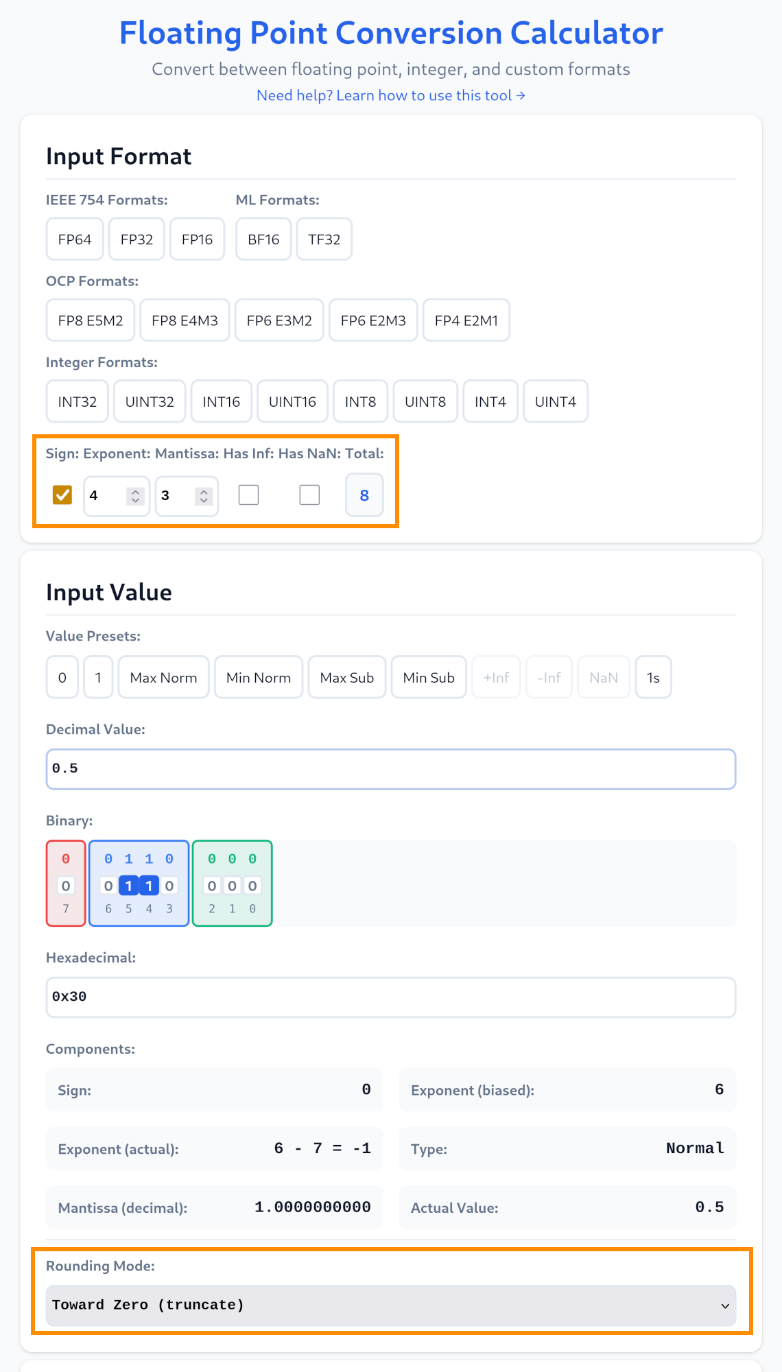
To generate a valid number you can use Spencer Williams Floating Point Number Converter. Setup a custom format with: Sign: True, Exponent: 4, Mantissa: 3, Has Inf: False, Has Nan: False and at the very bottom, Rounding Mode: Toward Zero (truncate). Input your desired decimal value and it tells you the binary or hexadecimal representation. You may also fiddle with the bits directly and see what the resulting floating point number is.
As the main goal of the project was to retime the lazily written HDL for optimal delay, the clock can be as high as 400 MHz. Although I'm not that confident that it will actually work at that speed. Also the poor little IO pads will probably not like that very much. Something like 50 MHz should be fine. Use way less (or even single clock it) to see the pipelining in action.
IO
| # | Input | Output | Bidirectional |
|---|---|---|---|
| 0 | a0 | y0 | b0 |
| 1 | a1 | y1 | b1 |
| 2 | a2 | y2 | b2 |
| 3 | a3 | y3 | b3 |
| 4 | a4 | y4 | b4 |
| 5 | a5 | y5 | b5 |
| 6 | a6 | y6 | b6 |
| 7 | a7 | y7 | b7 |