386 Herald
386 : Herald
- Author: Pranav M
- Description: A simple DSP Core for TinyTapeout
- GitHub repository
- Open in 3D viewer
- Clock: 50000000 Hz
Herald - Technical Documentation
Overview
Herald is a hardware digital signal processing (DSP) accelerator that combines two computational engines:
- CORDIC Unit - COordinate Rotation DIgital Computer for trigonometric operations
- MAC Unit - Multiply-Accumulate unit for arithmetic operations
The design provides 8 hardware-accelerated math operations accessible through a simple serial byte-oriented interface. All computations use Q12.12 fixed-point arithmetic (24-bit values: 12 integer bits + 12 fractional bits).
Architecture
Herald consists of three main components working together:
1. Control FSM
A finite state machine that manages the command/data protocol and orchestrates operations between the CORDIC and MAC engines. The FSM implements six states:
- IDLE - Waiting for command byte
- CMD_WRITE - Command received, ready for operands
- DATA_WRITE_A - Receiving first operand (3 bytes, LSB-first)
- DATA_WRITE_B - Receiving second operand (3 bytes, if needed)
- EXECUTE - Running computation (3-phase: start, wait_busy, get_result)
- RESULT_READY - Result available for byte-by-byte readout
2. CORDIC Engine (mkCORDICHighLevel)
Implements the CORDIC algorithm using iterative micro-rotations with only shifts and adds (no multipliers). The engine operates in two modes:
- Rotation Mode: Rotates a vector by a given angle (used for sin/cos)
- Vectoring Mode: Rotates a vector to align with x-axis (used for atan2, sqrt, normalize)
Each CORDIC operation completes in approximately 16-32 clock cycles depending on the precision required.
Supported Operations:
sin_cos(angle)- Simultaneous sine and cosine computationatan2(y, x)- Arctangent returning angle from coordinatessqrt_magnitude(x, y)- Vector magnitude √(x² + y²)normalize(x, y)- Returns normalized unit vector plus original magnitude
3. MAC Engine (mkMAC)
A fixed-point multiply-accumulate unit with internal accumulator register. Uses Bluespec-generated multipliers optimized for hardware synthesis.
Supported Operations:
multiply(a, b)- Simple multiplication (accumulator unchanged)mac(a, b)- Multiply-accumulate:acc += a × bmsu(a, b)- Multiply-subtract:acc -= a × bclear_accumulator()- Reset accumulator to zero
Block Diagram
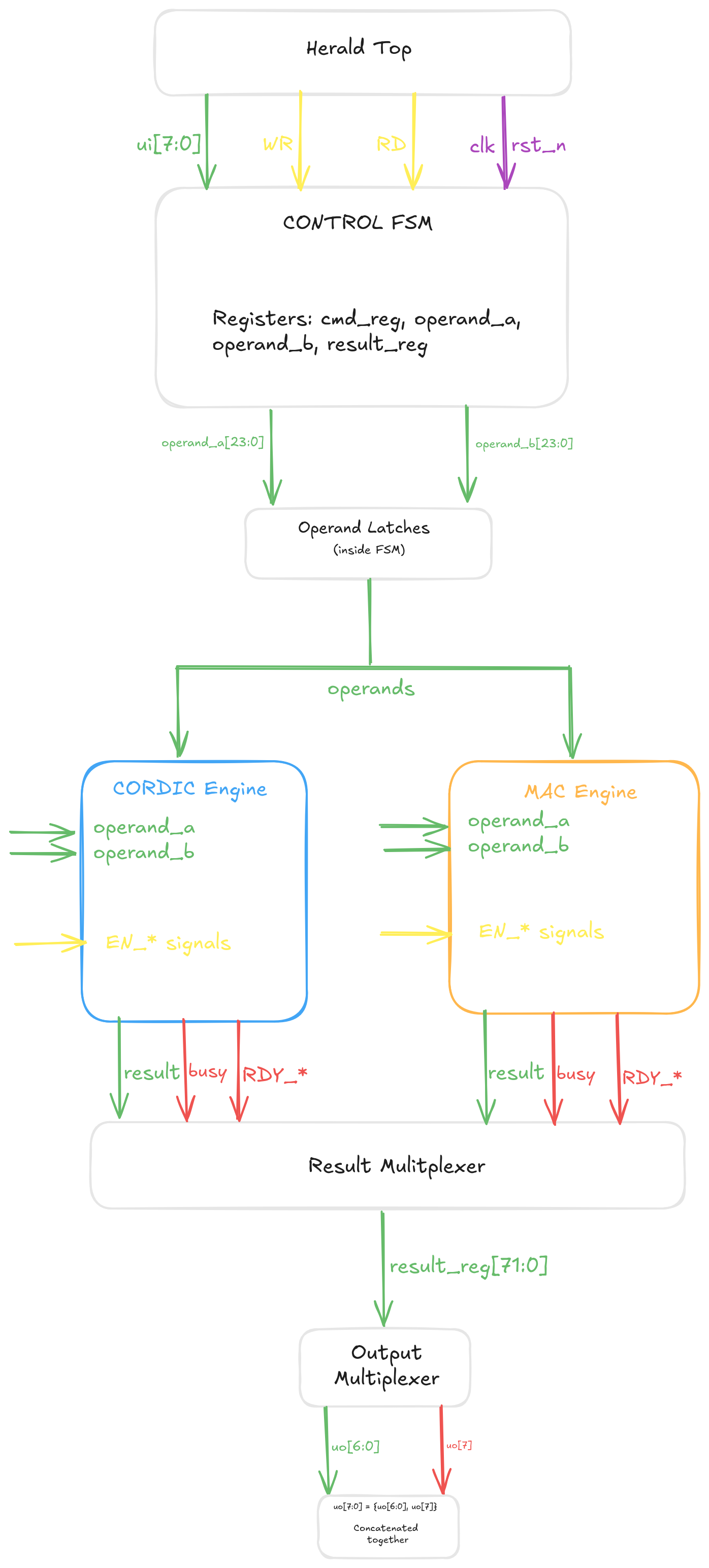
Figure 1: Herald architecture showing Control FSM, CORDIC Engine, MAC Engine, and data paths*
Interface Specification
Pin Assignment
| Pin Group | Direction | Width | Description |
|---|---|---|---|
ui[7:0] |
Input | 8 bits | Data/command input bus |
uo[7:0] |
Output | 8 bits | Data output bus<br>uo[7] = BUSY flag |
uio[0] |
Input | 1 bit | WR - Write strobe (rising edge trigger) |
uio[1] |
Input | 1 bit | RD - Read strobe (rising edge trigger) |
uio[7:2] |
Unused | 6 bits | Reserved for future use |
clk |
Input | 1 bit | System clock (up to 50 MHz) |
rst_n |
Input | 1 bit | Active-low asynchronous reset |
ena |
Input | 1 bit | Chip enable (TinyTapeout standard) |
Signal Descriptions
Input Data Bus (ui[7:0])
8-bit bidirectional bus for writing command bytes and operand data. Data is latched on the rising edge of the WR strobe.
Output Data Bus (uo[7:0])
8-bit output bus providing result data and status:
- Bits [6:0]: Result data (when BUSY = 0)
- Bit [7]: BUSY flag
1= Herald is processing a command (busy)0= Herald is idle or result ready for reading
Write Strobe (uio[0])
Rising edge triggers data capture from ui[7:0]. Used to write command bytes and operand bytes.
Read Strobe (uio[1])
Rising edge triggers output of next result byte on uo[7:0]. Used to read result data byte-by-byte.
Reset Behavior
On reset (rst_n = 0):
- FSM returns to IDLE state
- All registers cleared (command, operands, results)
- BUSY flag set to 0
- Output bus set to 0x00
- Both CORDIC and MAC engines reset
Communication Protocol
Herald uses a serial byte-oriented protocol with write/read strobes for transferring commands, operands, and results.
Write Sequence (Host → Herald)
Step 1: Write Command Byte
1. Set ui[7:0] = command opcode (e.g., 0x10 for SINCOS)
2. Pulse uio[0] (WR) high then low (rising edge latches data)
3. Wait 1 clock cycle
4. Check uo[7] = 1 (BUSY flag set, FSM enters CMD_WRITE state)
Step 2: Write Operand Bytes
For each operand byte (always LSB-first, little-endian):
1. Set ui[7:0] = data byte
2. Pulse uio[0] (WR)
3. Wait 1 clock cycle
4. Repeat for all operand bytes

Operand A: 3 bytes (bits [7:0], [15:8], [23:16])
Operand B: 3 bytes (only if command requires second operand)
Step 3: Wait for Completion
1. Poll uo[7] until it becomes 0
2. Herald is now in RESULT_READY state
3. Result is available for reading
Read Sequence (Herald → Host)
Step 4: Read Result Bytes
For each result byte (LSB-first, little-endian):
1. Pulse uio[1] (RD)
2. Wait 1 clock cycle
3. Read uo[7:0] to get result byte
4. Repeat for all result bytes

After reading the last byte, Herald automatically returns to IDLE.
Command Operand Requirements
| Command | Operand A | Operand B | Result Bytes |
|---|---|---|---|
| SINCOS (0x10) | angle | - | 6 |
| ATAN2 (0x11) | y | x | 3 |
| SQRT (0x12) | x | y | 3 |
| NORMALIZE (0x13) | x | y | 9 |
| MULTIPLY (0x20) | a | b | 3 |
| MAC (0x21) | a | b | 3 |
| CLEAR (0x22) | - | - | 0 |
| MSU (0x23) | a | b | 3 |
FSM State Machine
The control FSM implements the following state transitions:
IDLE
  ↓ (WR strobe with command byte)
CMD_WRITE
  ↓ (WR strobe with operand bytes)
DATA_WRITE_A (receive operand A, 3 bytes)
  ↓ (if command needs operand B)
DATA_WRITE_B (receive operand B, 3 bytes)
  ↓
EXECUTE (3 phases: start → wait_busy → get_result)
  ↓
RESULT_READY (output bytes on RD strobe)
  ↓ (after last byte read)
IDLE
State Descriptions
IDLE
- Waiting for command byte
- BUSY = 0
- Transitions on WR strobe
CMD_WRITE
- Command byte received
- BUSY = 1
- Determines if operands needed
- CLEAR command skips directly to EXECUTE
DATA_WRITE_A
- Collecting first operand (3 bytes)
- Bytes stored LSB-first
- After 3rd byte, checks if operand B needed
DATA_WRITE_B
- Collecting second operand (3 bytes)
- Only for commands requiring two operands
- After 3rd byte, transitions to EXECUTE
EXECUTE
- Three-phase execution:
- Phase 0: Assert start enable signal to CORDIC or MAC
- Phase 1: Wait for engine busy flag to clear
- Phase 2: Assert get_result enable and latch result
- Transitions to RESULT_READY when result captured
RESULT_READY
- Result available for reading
- BUSY = 0
- Each RD strobe outputs next byte
- Returns to IDLE after last byte read
State Diagram
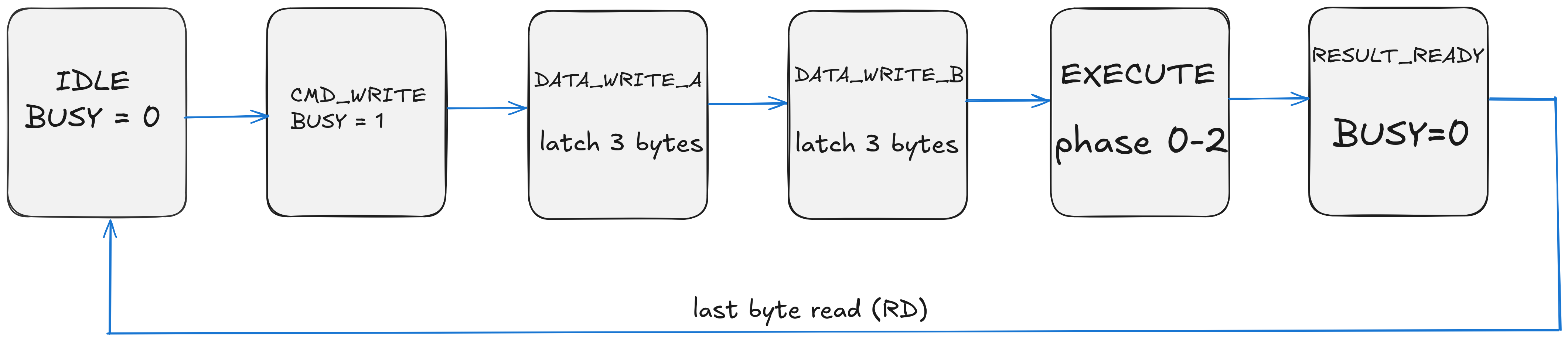
Figure 2: FSM state transitions for command processing*
Data Format: Q12.12 Fixed-Point
All operands and results use 24-bit Q12.12 fixed-point representation:
Bit Layout:
[23]     [22:12]      [11:0]
Sign     Integer      Fractional
1 bit    11 bits      12 bits
Format Details
- Sign bit [23]: 0 = positive, 1 = negative (two's complement)
- Integer bits [22:12]: Signed integer part (range: -2048 to +2047)
- Fractional bits [11:0]: Unsigned fractional part (units of 1/4096)
Numeric Range and Resolution
- Range: -2048.0 to +2047.999755859375
- Resolution: 1/4096 ≈ 0.000244140625
- Smallest positive value: 0x000001 = 1/4096
- Largest positive value: 0x7FFFFF ≈ 2047.9998
- Most negative value: 0x800000 = -2048.0
Encoding Examples
| Decimal Value | Hex (Q12.12) | Binary Breakdown |
|---|---|---|
| 0.0 | 0x000000 | 0 00000000000 000000000000 |
| 1.0 | 0x001000 | 0 00000000001 000000000000 |
| 0.5 | 0x000800 | 0 00000000000 100000000000 |
| -1.0 | 0xFFF000 | 1 11111111111 000000000000 |
| 3.14159 | 0x003243 | 0 00000000011 001001000011 |
| π/2 (1.5708) | 0x001921 | 0 00000000001 100100100001 |
| -0.25 | 0xFFFC00 | 1 11111111111 110000000000 |
Conversion Functions
Floating-point to Q12.12:
int32_t float_to_q12_12(float value) {
    return (int32_t)(value * 4096.0f);
}
Q12.12 to floating-point:
float q12_12_to_float(int32_t q_value) {
    return (float)q_value / 4096.0f;
}
Byte Order (Endianness)
All multi-byte values are transmitted LSB-first (little-endian):
- Byte 0: Bits [7:0] (least significant)
- Byte 1: Bits [15:8]
- Byte 2: Bits [23:16] (most significant)
Example: Value 0x003243 (π ≈ 3.14159) is transmitted as:
Byte 0: 0x43
Byte 1: 0x32
Byte 2: 0x00
Command Reference
CORDIC Commands
0x10: CORDIC_SINCOS
Compute sine and cosine of an angle simultaneously
Operands:
angle(3 bytes, Q12.12, radians)
Result: 6 bytes
- Bytes 0-2:
sin(angle)(Q12.12) - Bytes 3-5:
cos(angle)(Q12.12)
Range: Input angle should be in range [-π, +π] for best accuracy. Values outside this range will wrap.
Example:
Input:  angle = π/4 ≈ 0.7854 = 0x000C91
Output: sin = 0.707 ≈ 0x000B50
        cos = 0.707 ≈ 0x000B50
0x11: CORDIC_ATAN2
Compute arctangent of y/x (angle from coordinates)
Operands:
y(3 bytes, Q12.12)x(3 bytes, Q12.12)
Result: 3 bytes
- Angle in radians (Q12.12), range [-π, +π]
Special Cases:
- If x = 0 and y > 0: returns +π/2
- If x = 0 and y < 0: returns -π/2
- If x = 0 and y = 0: returns 0
Example:
Input:  y = 1.0 = 0x001000
        x = 1.0 = 0x001000
Output: angle = π/4 ≈ 0.7854 = 0x000C91
0x12: CORDIC_SQRT
Compute magnitude of vector (x, y) using √(x² + y²)
Operands:
x(3 bytes, Q12.12)y(3 bytes, Q12.12)
Result: 3 bytes
- Magnitude (Q12.12)
Note: Both x and y are squared internally, so sign doesn't affect result. This is effectively computing the Euclidean distance from origin.
Example:
Input:  x = 3.0 = 0x003000
        y = 4.0 = 0x004000
Output: magnitude = 5.0 = 0x005000
0x13: CORDIC_NORMALIZE
Normalize vector and return both normalized components plus magnitude
Operands:
x(3 bytes, Q12.12)y(3 bytes, Q12.12)
Result: 9 bytes
- Bytes 0-2:
x_normalized(Q12.12, unit vector x-component) - Bytes 3-5:
y_normalized(Q12.12, unit vector y-component) - Bytes 6-8:
magnitude(Q12.12, original vector length)
Properties:
- x_normalized² + y_normalized² ≈ 1.0
- x = x_normalized × magnitude
- y = y_normalized × magnitude
Example:
Input:  x = 3.0 = 0x003000
        y = 4.0 = 0x004000
Output: x_norm = 0.6 = 0x000999
        y_norm = 0.8 = 0x000CCD
        magnitude = 5.0 = 0x005000
MAC Commands
0x20: MAC_MULTIPLY
Simple fixed-point multiplication: result = a × b
Operands:
a(3 bytes, Q12.12)b(3 bytes, Q12.12)
Result: 3 bytes
- Product
a × b(Q12.12)
Note: Internal accumulator is not affected by this operation.
Example:
Input:  a = 2.5 = 0x002800
        b = 1.5 = 0x001800
Output: result = 3.75 = 0x003C00
0x21: MAC_MAC
Multiply-accumulate: accumulator += a × b
Operands:
a(3 bytes, Q12.12)b(3 bytes, Q12.12)
Result: 3 bytes
- New accumulator value (Q12.12)
Operation:
accumulator = accumulator + (a × b)
return accumulator
Use Cases:
- Dot products: Σ(aᵢ × bᵢ)
- FIR filters: Σ(coeffᵢ × sampleᵢ)
- Matrix multiplication
Example (accumulator starts at 0):
Call 1: a = 1.0, b = 2.0 → acc = 2.0 = 0x002000
Call 2: a = 3.0, b = 1.0 → acc = 5.0 = 0x005000
Call 3: a = 0.5, b = 4.0 → acc = 7.0 = 0x007000
0x22: MAC_CLEAR
Clear accumulator to zero
Operands: None
Result: None (returns to IDLE immediately)
Operation:
accumulator = 0
Use Cases:
- Reset before new MAC sequence
- Initialize for new computation
Example:
Write: CMD = 0x22
(No operands written, no result read, Herald returns to IDLE)
0x23: MAC_MSU
Multiply-subtract: accumulator -= a × b
Operands:
a(3 bytes, Q12.12)b(3 bytes, Q12.12)
Result: 3 bytes
- New accumulator value (Q12.12)
Operation:
accumulator = accumulator - (a × b)
return accumulator
Use Cases:
- Error correction algorithms
- Adaptive filters
- Subtractive synthesis
Example (accumulator = 10.0):
Input:  a = 2.0 = 0x002000
        b = 1.5 = 0x001800
Output: acc = 10.0 - 3.0 = 7.0 = 0x007000
Testing and Verification
Herald includes comprehensive cocotb testbenches covering:
Protocol Tests (test_wrapper.py)
- Command write sequences
- Operand byte ordering
- BUSY flag behavior
- Result readback
- FSM state transitions
CORDIC Tests (test_cordic.py)
- Trigonometric accuracy (sin/cos)
- Angle calculation (atan2)
- Magnitude computation (sqrt)
- Vector normalization
- Edge cases (zero vectors, negative values)
MAC Tests (test_mac.py)
- Multiplication accuracy
- Accumulator operations
- Overflow behavior
- Clear functionality
- Multi-step accumulation
Design Notes
CORDIC Algorithm Implementation
The CORDIC engine uses a table of pre-computed arctangent values for each iteration:
atan(2^-i) for i = 0, 1, 2, ..., 23
Each iteration performs:
x_new = x - y × d × 2^(-i)
y_new = y + x × d × 2^(-i)
z_new = z - d × atan(2^(-i))
where d ∈ {-1, +1} is the rotation direction determined by the sign of the remaining angle.
Fixed-Point Multiplication
MAC operations multiply two Q12.12 values:
Q12.12 × Q12.12 → Q24.24 (48-bit intermediate)
Shift right 12 bits → Q12.12 (24-bit result)
The Bluespec-generated multiplier handles this automatically with proper rounding.
Clock Domain
All operations are fully synchronous to the input clock. No internal clock generation or clock domain crossings.
Reset Strategy
Asynchronous reset (rst_n) for reliable startup. All registers have defined reset values.
IO
| # | Input | Output | Bidirectional |
|---|---|---|---|
| 0 | Command/Data input bit 0 | Data output bit 0 | Unused |
| 1 | Command/Data input bit 1 | Data output bit 1 | Unused |
| 2 | Command/Data input bit 2 | Data output bit 2 | Unused |
| 3 | Command/Data input bit 3 | Data output bit 3 | Unused |
| 4 | Command/Data input bit 4 | Data output bit 4 | Unused |
| 5 | Command input bit 5 | Data output bit 5 | Unused |
| 6 | Command input bit 6 | Data output bit 6 | Unused |
| 7 | Command input bit 7 | Data output bit 7 | Unused |