238 Glitcher
238 : Glitcher

- Author: Philip Åkesson
- Description: Fault injection pulse generator with trigger input and configurable parameters, controllable over UART.
- GitHub repository
- Open in 3D viewer
- Clock: 50000000 Hz
Introduction
This project is a pulse generator with configurable parameters, intended for use in voltage or electromagnetic fault injection attacks.
Fault injection is a hardware attack technique in which a brief disruption to a microcontroller's power supply or electromagnetic environment creates faults (glitches) that can cause it to skip instructions, corrupt computations, or bypass security checks. This can be used to potentially reveal cryptographic keys, bypass secure boot, or unlock otherwise inaccessible functionality.
In a typical voltage fault injection setup, the target microcontroller's power rail is momentarily pulled low (or sometimes spiked high) for a tiny fraction of a second. If timed correctly, this can cause a single instruction to execute incorrectly or not at all.
Similarly, electromagnetic fault injection (EMFI) uses a coil placed near the target IC to induce transient currents in the die.
In practice, the correct glitch parameters are rarely known in advance. The useful fault parameters often have to be found experimentally by sweeping across different delay values, pulse widths, pulse counts, and pulse spacing until the target shows an interesting response.
The pulse generator can be configured and controlled over a standard UART serial connection at 115200 baud, making it easy to drive from a microcontroller, a single-board computer like a Raspberry Pi, or a USB-to-serial adapter.
Pulses can be triggered either by UART commands or by an external trigger input.
The pulse generator runs at 50 MHz, giving a timing resolution of 20 ns. This is sufficient for precise, repeatable glitch placement on a wide range of targets.
Hardware Interface
Inputs
| Pin | Signal | Description |
|---|---|---|
ui[0] |
Trigger In | External hardware trigger. When the trigger is armed, a high signal on this pin starts the pulse sequence. |
ui[1] |
UART RX | Serial input from the host (115200 8N1). Connect to your host's TX pin. |
Outputs
| Pin | Signal | Description |
|---|---|---|
uo[0] |
UART TX | Serial output to the host (115200 8N1). Connect to your host's RX pin. |
uo[1] |
Pulse Out | Glitch pulse output, active high. |
uo[2] |
Target Reset | Target power-cycle output, active high. Hold high for the configured reset duration. |
uo[3] |
Pulse EN | Single-cycle strobe, goes high for one clock cycle (20 ns) at the start of each triggered glitch sequence. Useful for oscilloscope triggering. |
uo[4] |
Busy | High whenever the glitcher is executing a sequence (reset, delay, pulse, or spacing). Low only when idle. |
uo[5] |
Armed | High when the hardware trigger input is armed and waiting for a high signal on ui[0]. |
uo[6] |
Pulse Out or Target Reset | Active high during both glitch pulse output and target reset. |
uio[0] |
Pulse Out (Inverted) | Inverted version of uo[1]. Use with active-low circuits or MOSFET drivers that require an inverted input. |
uio[1] |
Target Reset (Inverted) | Inverted version of uo[2]. |
External Hardware
The Pulse Out (uo[1]) output can be used with an N-channel MOSFET or analog multiplexer/switch for voltage fault injection, or connected to a ChipSHOUTER for EMFI.
Use Pulse Out (Inverted) (uio[0]) when your driver circuit expects an active-low enable signal.
In cases where the pulse output might drive (all or parts of) a target during reset, use the combined Pulse Out or Target Reset (uo[6]) output, which is high during both pulse generation and target reset.
To use the Target Reset (or Target Reset (Inverted)), connect it to a suitable reset pin or a power switch for the entire target.
UART Protocol
All communication is at 115200 baud, 8N1 (8 data bits, no parity, 1 stop bit). Commands are single bytes, optionally followed by parameter bytes for configuration values. All multi-byte parameters are big-endian (high byte first).
All parameter values are either 8-bit or 16-bit unsigned integers.
All timing values are specified in clock cycles at 50 MHz, where 1 cycle = 20 ns.
The minimum effective duration for all timing parameters is 1 clock cycle (20 ns). Both 0 and 1 produce a 1-cycle duration; to set a 2-cycle duration, use the value 2, and so on.
The maximum value for 8-bit timing parameters is 5.10 µs, while the 16-bit timing parameters go up to 1.31 ms.
Configuration
Configuration commands only update the stored parameter values.
| Command | Byte | Parameters | Default | Description |
|---|---|---|---|---|
d |
0x64 |
2 bytes (16-bit) | 0x0000 |
Set delay before first pulse |
w |
0x77 |
1 byte (8-bit) | 0x01 |
Set pulse width |
n |
0x6E |
1 byte (8-bit) | 0x01 |
Set number of pulses |
s |
0x73 |
2 bytes (16-bit) | 0x0000 |
Set spacing between pulses |
r |
0x72 |
2 bytes (16-bit) | 0x0000 |
Set target reset duration |
Actions
| Command | Byte | Parameters | Default | Description |
|---|---|---|---|---|
t |
0x74 |
none | — | Trigger pulse sequence |
a |
0x61 |
none | — | Toggle arm/disarm |
p |
0x70 |
none | — | Reset (power cycle) target using the configured reset duration. |
Reset Modes
The reset mode determines what happens after the target reset command has completed. By default, a pulse sequence is started directly after resetting the target, but it is also possible to set the armed state and wait for a trigger input, or do nothing at all.
| Command | Byte | Parameters | Default | Description |
|---|---|---|---|---|
u |
0x75 |
none | — | Reset mode: Pulse (default) |
i |
0x69 |
none | — | Reset mode: Arm |
y |
0x79 |
none | — | Reset mode: None |
Other
| Command | Byte | Parameters | Default | Description |
|---|---|---|---|---|
h |
0x68 |
none | — | Hello! Returns Erika |
| other | — | — | — | Unknown commands are echoed back over UART |
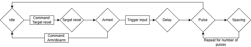
How It Works
Internally, the glitcher is implemented as a small state machine with five main phases: idle, target reset, delay, pulse active, and pulse spacing. The Busy (uo[4]) output is high whenever the design is not idle, the Armed (uo[5]) output is high when the external trigger path is waiting for Trigger In (ui[0]), and Pulse EN (uo[3]) generates a one-clock strobe at the moment a pulse sequence starts.
When in the target reset state, the Target Reset (uo[2]) output is high.
When in the pulse active state, the Pulse Out (uo[1]) output is high.
Note that the trigger input is synchronized internally, so there is an initial delay of two clock cycles before starting the pulse sequence. The pulse sequence then has a minimum of one additional delay cycle before the pulse output goes high, giving a minimum time from trigger input to pulse output of 60-80 ns (three to four clock cycles), depending on the timing of the trigger, when configured with zero additional delay.
The trigger is activated when Trigger In (ui[0]) is high, not just on a rising edge. This means that if the trigger input is set to a constant high signal, the system will trigger as soon as the synchronized trigger is seen after arming.
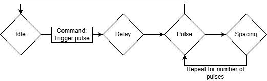
Manual Trigger Over UART
In the simplest use case, the host first configures the pulse parameters over UART and then sends the t command to start a sequence immediately. The glitcher waits for the configured delay, generates the requested number of pulses with the configured width and spacing, and then returns to the idle state.
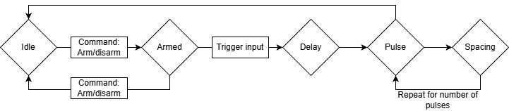
Arm Over UART, External Trigger Input
For external trigger inputs, the host sends a to arm the trigger logic. The glitcher then waits in the idle state with Armed (uo[5]) high until Trigger In (ui[0]) goes high, at which point it starts the same delay-and-pulse sequence as a manual UART trigger. Arming is automatically cleared when the sequence begins, so each arm command corresponds to one trigger event.
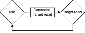
Reset Mode: None
When reset mode is set to None, the p command only asserts Target Reset (uo[2]) for the configured reset duration. After that time has passed, the glitcher returns directly to idle without generating any pulse sequence and without arming the external trigger input.
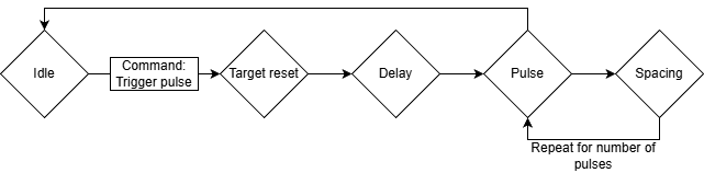
Reset Mode: Pulse
When reset mode is set to Pulse, the p command first resets the target and then automatically starts the configured pulse sequence. After reset is released, the normal pulse delay is still applied before the first pulse, which makes it possible to place the glitch at a controlled offset relative to the end of the reset interval.
This is the default reset mode.
Reset Mode: Arm
When reset mode is set to Arm, the p command resets the target and then returns to idle with the trigger logic armed. This is useful when the target should be reset first, but the actual glitch should not occur until a later external event on Trigger In (ui[0]).
How to Test
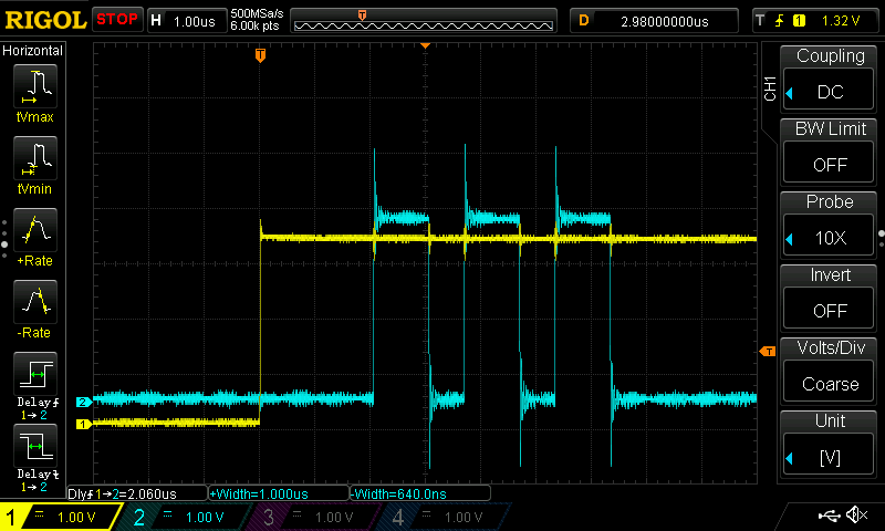
All examples and oscilloscope captures in this section were taken with the project running on a Lattice UP5K FPGA on the Tiny Tapeout FPGA Breakout.
Basic Use Cases
The project can be tested by connecting a microcontroller or USB-to-serial adapter to the UART RX and TX pins (ui[1] and uo[0], respectively).
First, test that the UART works by sending x (hex byte 78), which should be echoed back because it is an unknown command, or h, which should return the string Erika.
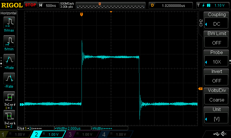
To test a basic pulse, set the pulse width to 100 clock cycles (2 μs) with w\x64 (hex bytes 77 64) and trigger the pulse with t (hex byte 74). This should result in a pulse on the Pulse Out pin (uo[1]).
Full sequence:
w 0x64
t
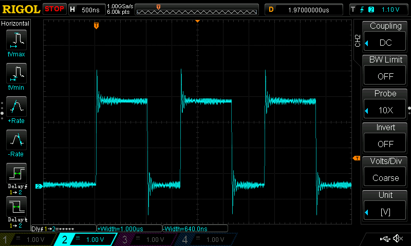
To test multiple pulses, set the width to 50 clock cycles (1 μs) with w\x32 (hex bytes 77 32), spacing to 32 clock cycles (640 ns) with s\x00\x20 (hex bytes 73 00 20) and number of pulses to 3 with n\x03 (hex bytes 6E 03), then trigger the pulse with t (hex byte 74).
Full sequence:
w 0x32
s 0x00 0x20
n 0x03
t
To test trigger arming, send a (hex byte 61). This should make the armed pin (uo[5]) go high.
Sending a again should disarm the trigger. While armed, setting the trigger input pin (ui[0]) to high will trigger a pulse sequence with the configured parameters.
Full sequence:
w 0x32
s 0x00 0x20
n 0x03
a
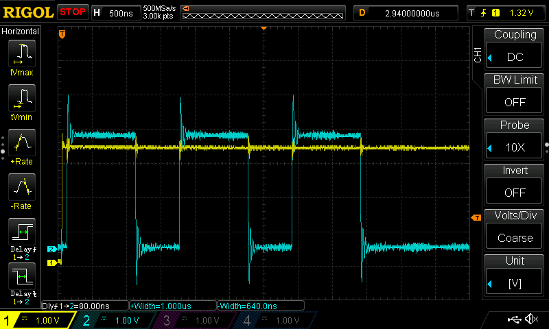
This can be combined with a delay. Set the delay to 100 clock cycles (2 μs) with d\x00\x64 (hex bytes 64 00 64), pulse width to 50 clock cycles (1 μs) with w\x32 (hex bytes 77 32), spacing to 32 clock cycles (640 ns) with s\x00\x20 (hex bytes 73 00 20) and number of pulses to 3 with n\x03 (hex bytes 6E 03).
Arm with a (hex byte 61) and then set the trigger input pin (ui[0]) to high.
Full sequence:
d 0x00 0x64
w 0x32
s 0x00 0x20
n 0x03
a
See the cocotb tests for more examples.
Using with MicroPython on the TT Demo Board
The Tiny Tapeout demo board includes an RP2350 running MicroPython, which can be used to test most of the functionality.
First, set mode = ASIC_RP_CONTROL in config.ini (or manually in the REPL) to allow the RP2350 to drive the project inputs.
To use UART from the MicroPython REPL, initialize it like this:
>>> from machine import UART
>>> uart = UART(0, baudrate=115200, tx=tt.pins.ui_in1.raw_pin, rx=tt.pins.uo_out0.raw_pin)
>>> _ = uart.read() # Clear read buffer
The h command can be used to verify that the project is running:
>>> uart.write(b'h')
1
>>> uart.read()
b'Erika'
Unknown commands are echoed back directly:
>>> uart.write(b'x')
1
>>> uart.read()
b'x'
The Armed signal can be found on uo[5], and the trigger input is on ui[0].
Here is a quick sanity check for these:
>>> tt.uo_out[5]     # Check if armed (0 = not armed, 1 = armed)
<Logic ('0')>
>>> uart.write(b'a') # Arm trigger
1
>>> tt.uo_out[5]     # Trigger is now armed
<Logic ('1')>
>>> tt.ui_in[0] = 1  # Set the trigger input
>>> tt.uo_out[5]     # No longer armed
<Logic ('0')>
Acknowledgments and Similar Projects
This project had several sources of inspiration, including:
- The "NXP LPC1343 Bootloader Bypass" series of blog posts by Dmitry Nedospasov is where I first saw this type of glitcher implemented in an FPGA.
- The Wallet.fail presentation at 35C3 (watch the presentation on YouTube), by Thomas Roth, Dmitry Nedospasov, and Josh Datko, used a very similar FPGA glitcher.
- ... and so did the Chip.Fail presentation at Black Hat USA 2019, by Thomas Roth and Josh Datko. The code for this can be found on GitHub.
- I attended one of Dmitry's in-person "Hardware hacking with FPGAs" training courses in 2019 as well, which was also a great source of inspiration.
If you are looking for fault injection tooling that works out-of-the-box, also check out the ChipWhisperer by Colin O'Flynn (NewAE Technology) or the Faultier by Thomas Roth (Hextree.io).
IO
| # | Input | Output | Bidirectional |
|---|---|---|---|
| 0 | Trigger Input | UART TX | Pulse Out (Inverted) |
| 1 | UART RX | Pulse Out | Target Reset (Inverted) |
| 2 | Target Reset | ||
| 3 | Pulse EN | ||
| 4 | Busy | ||
| 5 | Armed | ||
| 6 | Pulse Out or Target Reset | ||
| 7 |