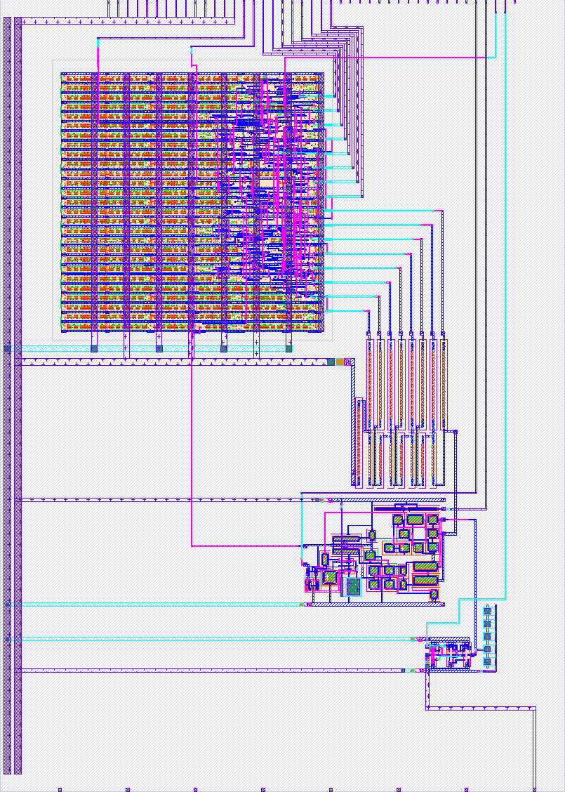
484 8 Bit SAR ADC
484 : 8 Bit SAR ADC
- Author: Eric Estevez
- Description: Convert analog signal to digital
- GitHub repository
- Open in 3D viewer
- Clock: 0 Hz
How it works
The goal of the project is to make an 8-bit resolution SAR ADC similar to a group project I did in college.
The design currently does not have full rail-to-rail detection without precise timing. If I can make a good feedback system for the comparator while not relying on timing restrictions, I will update the design.
Without any requirements for recalibration, the circuit detects and outputs voltages accurately for the system approximately in the range of 0.8V to VCC. The sampling circuit will hold the analog input value until the positive edge of its clock cycle which feeds its output to the comparator. The comparator outputs a value based on if the DAC output is higher or lower than the sampled input (if DAC is higher, it outputs low; if DAC is lower, it outputs high). The output is fed to the digital logic block which checks whether the comparison bit needs to change so that the value outputted by the block converges to the sampled analog signal.
How to test
Input an analog signal to the analog input pin. Because I currently don't have a clock divider, there will need to be two clock signals, one in the digital logic clock input, and another that's at least 8 times as slow to the clock pin for the sampled input. The enable signal and calibration signal can be used to tune the comparator for low input signals, but I currently do not have a good enough feedback system to track it accurately. Currently they are just used to reset the comparator signal levels. Without those signals changing according to the input level, the comparator can only output accurately above approximately 0.8V.
External hardware
Signal generator, oscilloscope
IO
| # | Input | Output | Bidirectional |
|---|---|---|---|
| 0 | comparator enable | sar bit 0 | sar clock |
| 1 | comparator calibration | sar bit 1 | comp done |
| 2 | sar bit 2 | ||
| 3 | sar bit 3 | ||
| 4 | sar bit 4 | ||
| 5 | sar bit 5 | ||
| 6 | sar bit 6 | ||
| 7 | sar bit 7 |
Analog pins
ua | PCB Pin | Internal index | Description |
|---|---|---|---|
| 0 | A4 | 4 | sample in |