965 Traffic Light Controller
965 : Traffic Light Controller
- Author: Maximilian Kernmaier
- Description: A digital traffic light controller with pedestrian request handling and MAX7219 display interface.
- GitHub repository
- Open in 3D viewer
- Clock: 1000000 Hz
How it works
This project implements a digital traffic light controller with integrated pedestrian request logic and MAX7219 LED display output.
The system coordinates car and pedestrian lights with precise timing, button debouncing, and a visual countdown before the pedestrian green phase.
In addition to the countdown, the LED matrices display different smiley faces corresponding to the current pedestrian signal:
- 😀 Happy face for green
- 😐 Neutral face for blinking green
- ☹️ Sad face for red
If pedestrians have to wait during the red phase, they can trigger an early green phase by pressing the request button. The countdown will start immediately, and the request indicator light will turn on once the system acknowledges the input.
When the pedestrian phase is about to activate, the final 9 seconds are displayed on the LED matrices driven by the MAX7219 interface.
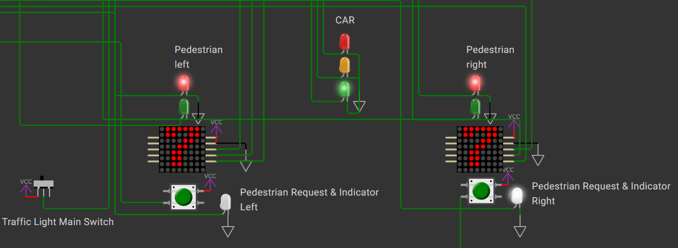
The design operates on a 1 MHz input clock. To verify its behavior, the circuit was simulated using GTKWave and additionally validated in Wokwi with a custom chip module (see the figure below).
This provides high confidence that the design will also function correctly when fabricated — or at least, that’s the hope 🙂
The design is entirely written in Verilog and organized into several modules:
- A Finite State Machine (FSM) controlling light transitions and timing
- A clock-enable divider generating precise timing intervals
- A dedicated MAX7219 driver for configuration and data transfer
- A SPI master handling communication with the MAX7219
The full Verilog implementation and testbenches are available on GitHub.
This project demonstrates how real-world traffic-light logic can be implemented purely in Verilog —
including timing control, state management, and SPI-driven display output, all within a compact TinyTapeout design.
How to test
-
Connect LEDs to the car and pedestrian light output pins (
uo[0]–uo[6]):uo[0]→ Car reduo[1]→ Car yellowuo[2]→ Car greenuo[3]→ Pedestrian red (right)uo[4]→ Pedestrian green (right)uo[5]→ Pedestrian red (left)uo[6]→ Pedestrian green (left)
-
Connect switches or pushbuttons to the input pins:
ui[0]→ Main ON/OFF switchui[1]→ Pedestrian request (left)ui[2]→ Pedestrian request (right)
-
Connect two MAX7219 LED modules via
uio[0:5]:uio[0]→ DIN (left module)uio[1]→ CLK (left module)uio[2]→ CS (left module)uio[3]→ DIN (right module)uio[4]→ CLK (right module)uio[5]→ CS (right module)uio[6]→ Pedestrian request indicator (left)uio[7]→ Pedestrian request indicator (right)
-
Power on the system and observe the automatic light sequence and the countdown timing on the displays.
Also verify the operation of the request indicators and the main power switch. -
The design can also be simulated using GTKWave together with the testbench
traffic_light_tb.vlocated in thetestfolder.
Make sure the global defineSIMis enabled before running the simulation.
External hardware
- LEDs for car, pedestrian, and early-request indicators
- Pushbuttons for pedestrian requests
- A toggle switch for the main power control
- Two MAX7219 LED matrix modules (FC16 type) for the visual countdown display
IO
| # | Input | Output | Bidirectional |
|---|---|---|---|
| 0 | Main ON/OFF Switch | Car red light | DIN (MAX7219 left) |
| 1 | Pedestrian request button (left) | Car yellow light | CS (MAX7219 left) |
| 2 | Pedestrian request button (right) | Car green light | SCLK (MAX7219 left) |
| 3 | Pedestrian red light (left) | DIN (MAX7219 right) | |
| 4 | Pedestrian green light (left) | CS (MAX7219 right) | |
| 5 | Pedestrian red light (right) | SCLK (MAX7219 right) | |
| 6 | Pedestrian green light (right) | Pedestrian request indicator (left) | |
| 7 | Pedestrian request indicator (right) |