271 Onchip - Ring VCO 11 stages x2
271 : Onchip - Ring VCO 11 stages x2
- Author: Jorge Angarita
- Description: Two identical 11-stages ring oscillator voltage controled oscillator
- GitHub repository
- Open in 3D viewer
- Clock: 0 Hz
How it works
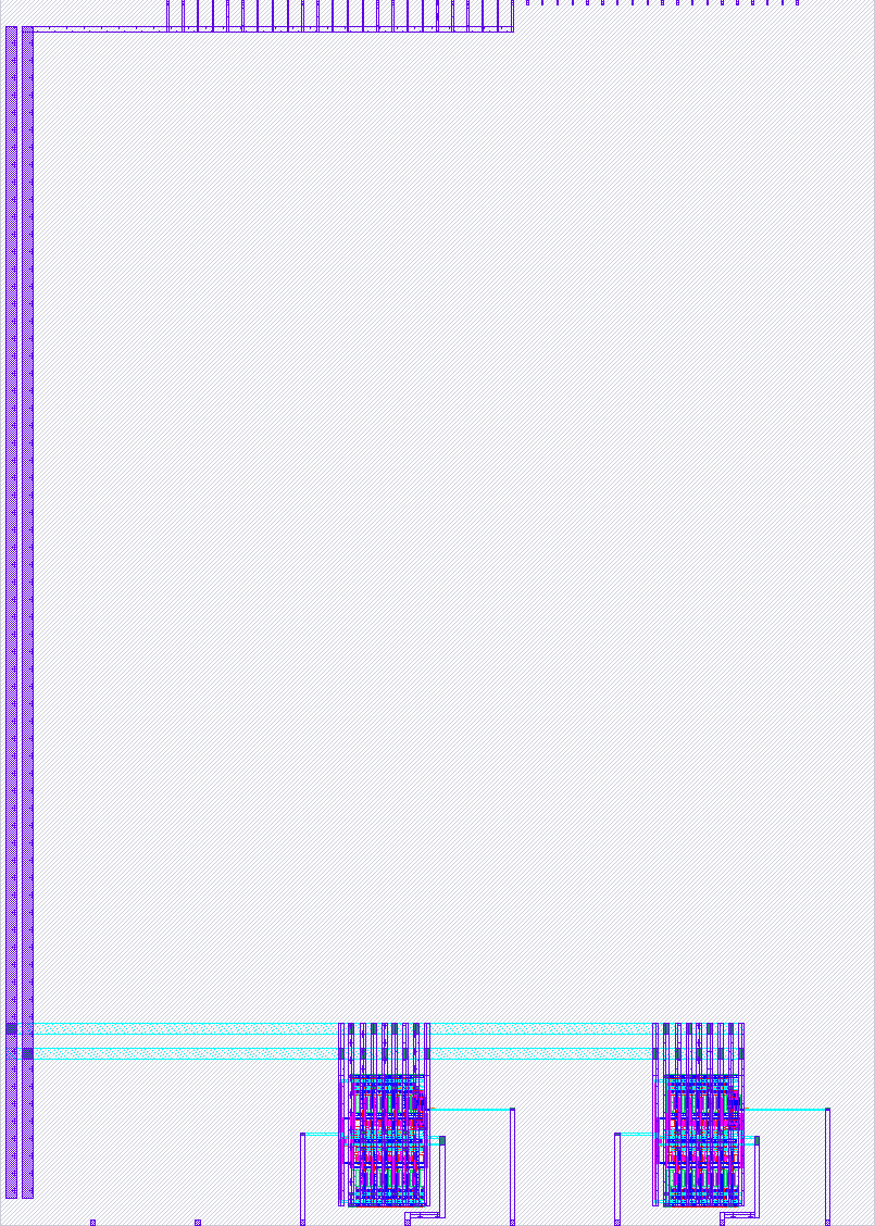
The circuit is an 11-stage ring oscillator voltage-controlled oscillator (RVCO). The basic oscillating stage consists of current-starved inverters controlled by an external input, VCTRN. Additionally, there is a VRST pulse input that runs or stops the oscillator when it receives a low or high value. One of its phases is buffered and connected as an output.
The submission includes two oscillators. The first three analog pins are associated with the first oscillator in the following order: OUT, VCTRN, and VRST. The other three are associated with the second oscillator in the same order.
How to test
First, activate the oscillator by setting the corresponding VRST to GND. Then, set the VCTRN node to a relatively high analog value. For testing purposes, the test benches were done using Vctrn = 0.9 V. Then, measure the OUT node to obtain a pulse signal.
External hardware
- Voltage Source
- Oscilloscope
IO
| # | Input | Output | Bidirectional |
|---|---|---|---|
| 0 | |||
| 1 | |||
| 2 | |||
| 3 | |||
| 4 | |||
| 5 | |||
| 6 | |||
| 7 |
Analog pins
ua | PCB Pin | Internal index | Description |
|---|---|---|---|
| 0 | B5 | 11 | out1 |
| 1 | B0 | 6 | vctrn1 |
| 2 | B4 | 10 | vrst1 |
| 3 | B1 | 7 | out2 |
| 4 | B3 | 9 | vctrn2 |
| 5 | B2 | 8 | vrst2 |