231 Nauta OTA with digital trimming
231 : Nauta OTA with digital trimming
- Author: Astria Nur Irfansyah
- Description: Simple Nauta OTA with 2-bit digital trimming
- GitHub repository
- Open in 3D viewer
- Clock: 0 Hz
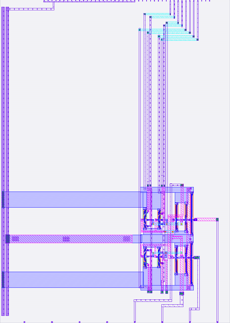
How it works
Nauta OTA with digital trim is based on the OTA circuit proposed by Bram Nauta. The digital trim is a subset of the digitally-tunable Nauta OTA described in [3]. One tuning implementation is described in [4].
[1] Nauta, B. (1993). Analog CMOS filters for very high frequencies. Springer US. https://doi.org/10.1007/978-1-4615-3580-5 [2] Nauta, B. (1992). A CMOS transconductance-C filter technique for very high frequencies. Solid-State Circuits, IEEE Journal Of, 27(2), 142–153. https://doi.org/10.1109/4.127337 [3] Nicholson, A. P., Iberzanov, A., Jenkins, J., Hamilton, T. J., & Lehmann, T. (2016). A Statistical Design Approach for a Digitally Programmable Mismatch-Tolerant High-Speed Nauta Structure Differential OTA in 65-nm CMOS. IEEE Transactions on Very Large Scale Integration (VLSI) Systems, PP(99), 1–12. https://doi.org/10.1109/TVLSI.2016.2526048 [4] Irfansyah, A. N., Nicholson, A. P., Iberzanov, A., Jenkins, J., Lehmann, T., & Hamilton, T. J. (2016). Automatic tuning of digitally-controllable positive-feedback OTAs in continuous-time sigma–delta modulators. Analog Integrated Circuits and Signal Processing, 89(2), 469–483. https://doi.org/10.1007/s10470-016-0820-3
How to test
Provide differential input ac signals, and observe output. Digital trimming is done through digital pins.
External hardware
External hardware not specifically required, other than normal test equipment.
IO
| # | Input | Output | Bidirectional |
|---|---|---|---|
| 0 | sw_p_A1 | ||
| 1 | sw_p_B1 | ||
| 2 | sw_p_A05 | ||
| 3 | sw_p_B05 | ||
| 4 | sw_n_A1 | ||
| 5 | sw_n_B1 | ||
| 6 | sw_n_A05 | ||
| 7 | sw_n_B05 |
Analog pins
ua | PCB Pin | Internal index | Description |
|---|---|---|---|
| 0 | A5 | 5 | in_p |
| 1 | A0 | 0 | in_n |
| 2 | A4 | 4 | out_p |
| 3 | A1 | 1 | out_n |