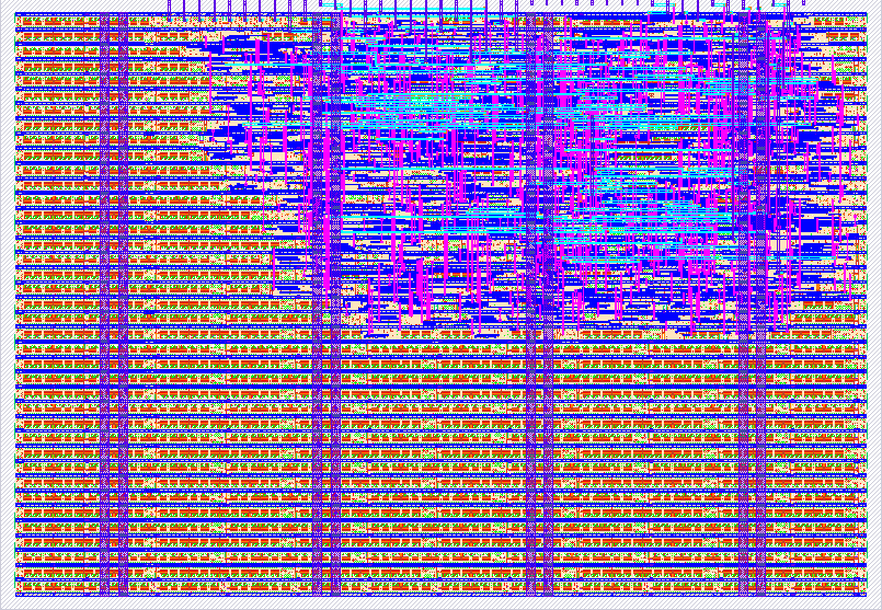
687 Tiny Turing Machine
687 : Tiny Turing Machine
- Author: Christoph Menz
- Description: A tiny Turing machine with configurable state transition table
- GitHub repository
- Open in 3D viewer
- Clock: 0 Hz
How it works
This project implements a Turing Machine on an ASIC with the following features:
Core Components
- 8-bit tape with configurable wrap-around mode
- 4 states (S0-S3) with unary alphabet ( Blank/0 and 1)
- State Transition Table (STT) with 4 banks:
- Bank 0: Unary Incrementer - Adds one "1" to a string of ones
- Bank 1: Bit Flipper - Inverts all bits from left to right
- Bank 2: Wall-E - Carries Bits from right side to left bound
- Bank 3: Custom - User-configurable STT
Operating Modes
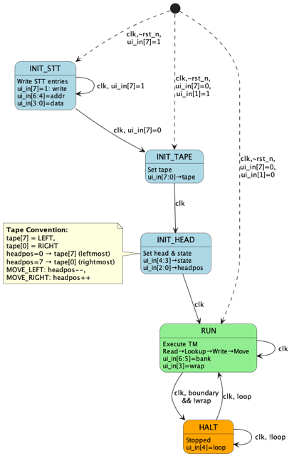
The machine operates in 5 distinct modes:
- INIT: Initial state after reset, loading configuration
- WRITE_TAPE: Writing initial tape values
- WRITE_HEAD: Setting head position and initial state
- RUN: Executing the Turing Machine program
- HALT: Machine stopped at boundary (unless wrap mode enabled)
Output Routing
Two 8-bit outputs are available:
- uo_out: Normally shows tape, or status when swapped
- uio_out: Normally shows status, or tape when swapped
Status format (8 bits):
[7:5]: Mode (0-4)[4:3]: Current state (0-3)[2:0]: Head position (0-7)
Head position: The status output can be switched to a (one hot) decoded head position output by setting ui_in[0]=1.
Swap control: ui_in[2]=1 swaps the outputs.
How to test
Quick Test (Preset 0: Unary Incrementer)
-
Reset with all inputs low:
ui_in = 00000000- Loads Bank 0 (Unary Incrementer) preset
- Initial tape:
11100000(three 1s on left) - Head at position 0 (leftmost)
- State 0
-
Clock slowly (manual or low frequency)
- Observe
uo_out(tape) changing - Expected behavior:
- Head moves right through the 1s
- Finds first 0, writes 1
- Result:
11110000(four 1s) - Machine halts at right boundary
- Observe
-
Observe outputs:
uo_out: Shows tape pattern (LEDs on bits 7-4)uio_out[7:5]: Mode (should be 3=RUN, then 4=HALT)uio_out[2:0]: Head position (counts 0→7)
Advanced Tests
Test Loop Mode (Auto-restart):
- Reset:
ui_in = 00010000(loop enabled, bit 4=1) - Clock continuously
- Machine will halt, then automatically restart with initial tape
- Observe repeating pattern
Test Wrap Mode (Endless tape):
- Reset:
ui_in = 00001000(wrap enabled, bit 3=1) - Clock continuously
- Head wraps around at boundaries, never halts
- Useful for Bank 1 (Bit Flipper) to see full tape processed
Test Custom STT:
- Reset:
ui_in = 10000000(manual mode, bit 7=1) - Write 8 STT entries:
- Example:
ui_in = 10000011writes0011(S0,1,R) to address 0 - Increment address bits [6:4] for each entry
- Example:
- Exit config:
ui_in = 00000000 - Set tape:
ui_in = 10101010 - Next clock: Set head/state:
ui_in = 00000011(state 0, position 3) - Run:
ui_in = 01100000(Bank 3, no wrap/loop)
Test Output Swap:
- Start any preset
- Toggle
ui_in[2]between 0 and 1 - Observe tape ↔ status swapping between
uo_outanduio_out
External hardware
For Tape Visualization:
- LED PMOD with 8 LEDs in a row
- 7-Segement-Display: might also be useful but not as intuitive
For Status Display:
- LED PMOD with 8 LEDs in a row
- Display mode(0-4), head position (0-7) and current state (0-3)
- With switch
ui_in[0]=1the one-hot decoded head position is shown
For Manual Control:
- DIP Switch
- Connect to
ui_in - Allows manual control of all settings:
- Switch 7: Config/Auto mode
- Switches 6-5: Bank selection
- Switch 4: Loop enable
- Switch 3: Wrap enable
- Switch 2: Output swap
- Switch 1: Manual tape init
- Switch 0: Head position decode
- Depending on mode allows also STT, Tape, Head and State configuration
- Connect to
- Clock button (for configuration and manual mode/state transistion)
- Reset button
IO
| # | Input | Output | Bidirectional |
|---|---|---|---|
| 0 | IN0_HEAD_DECODE | TP_ST_0 | ST_TP_0 |
| 1 | IN1_TAPE_INIT | TP_ST_1 | ST_TP_1 |
| 2 | IN2_OUTPUT_SWAP | TP_ST_2 | ST_TP_2 |
| 3 | IN3_WRAP_EN | TP_ST_3 | ST_TP_3 |
| 4 | IN4_LOOP_EN | TP_ST_4 | ST_TP_4 |
| 5 | IN5_BANK_SEL0 | TP_ST_5 | ST_TP_5 |
| 6 | IN6_BANK_SEL1 | TP_ST_6 | ST_TP_6 |
| 7 | IN7_CUSTOM_AUTO | TP_ST_7 | ST_TP_7 |