271 Current-Mode Bandgap Reference
271 : Current-Mode Bandgap Reference
- Author: Christoph Weiser
- Description: PVT stable reference voltage and current.
- GitHub repository
- Open in 3D viewer
- Clock: 0 Hz
How it works
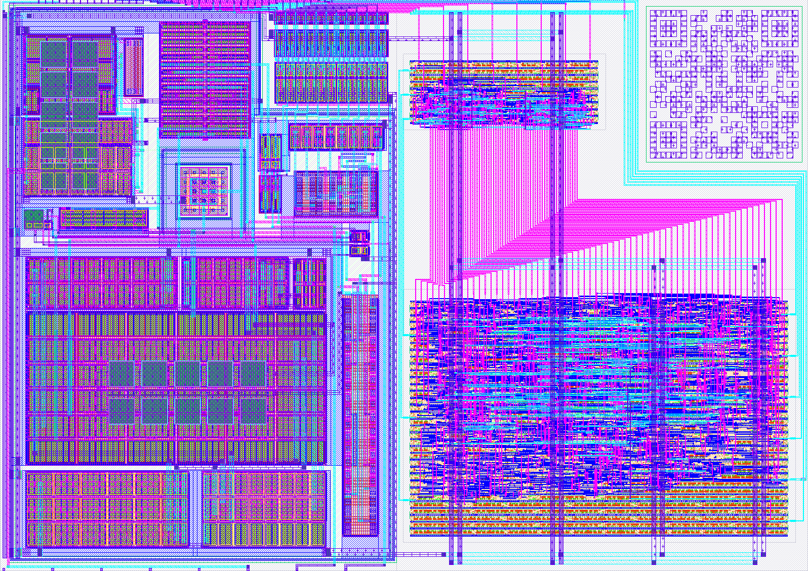
This circuit is a Current-Mode Bandgap Reference which is fully self-biased. It is powered from a nominal 3.3V supply.
It produces a 1V reference voltage and a 5.6uA output current.
In order to measure the very sensitive output voltage of the bandgap reference, a testbuffer is also included in the design. The testbuffer is biased from a external current source (~5uA) through pin ua[2].
To characterize the testbuffer a loop-through mechanism from ua[1] to ua[0] can be enabled. The test voltage can be applied to ua[1] and then measured back at ua[0].
The bandgap core can be enabled/disabled using the signal on uio_in[2].
To trim out process variations the core can be trimmed with a 8 bit correction resistor controlled from the tiny-tapeout managment area using ui_in[7:0].
How to test
Testing the testbuffer.
- Power VAPWR to 3.3V
- Apply ~5uA bias current to the testbuffer on ua[2]. SMU or 620kOhm from 3.3V.
- Apply external test voltage to input on ua[1].
- Route external voltage to testbuffer input. uio_in[0]=1
- Route buffered voltage to output. uio_in[1]=1
- Measure voltage back on ua[0].
Testing the bandgap voltage.
- Power VAPWR to 3.3V
- Apply ~5uA bias current to the testbuffer on ua[2]. SMU or 620kOhm from 3.3V.
- Enable bandgap core. uio_in[0]=1
- Route bandgap voltage to testbuffer input. uio_in[0]=0
- Route buffered bandgap voltage to output pin. uio_in[1]=1
- Measure voltage on ua[0].
Testing the reference current.
- Power VAPWR to 3.3V
- Enable bandgap core. uio_in[0]=1
- Route reference current to output pin. uio_in[1]=1
- measure current from ua[0] to GND.
External hardware
Multimeter to measure voltage and current.
Optional:
- Osciloscope to measure startup waveform.
- Precise power supply for VAPWR
- SMU for precission bias current.
- Oven to measure temperature stabililty.
IO
| # | Input | Output | Bidirectional |
|---|---|---|---|
| 0 | trim 7 | muxout 0 | Select Vext or Vbg |
| 1 | trim 6 | muxout 1 | Select Vbuf or Iout |
| 2 | trim 5 | muxout 2 | Enable bandgap core |
| 3 | trim 4 | muxout 3 | mosi |
| 4 | trim 3 | muxout 4 | miso |
| 5 | trim 2 | muxout 5 | cs |
| 6 | trim 1 | muxout 6 | sclk |
| 7 | trim 0 | muxout 7 |
Analog pins
ua | PCB Pin | Internal index | Description |
|---|---|---|---|
| 0 | B0 | 6 | Buffered output voltage or reference current |
| 1 | B1 | 7 | External test input voltage |
| 2 | B3 | 9 | Testbuffer bias current (~5uA) |