175 posit8_add
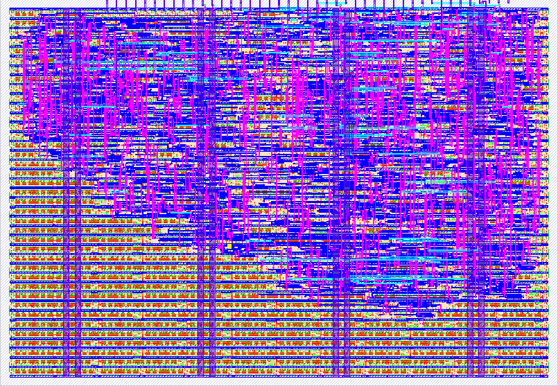
175 : posit8_add
- Author: Gustaf Swansen
- Description: Addition circuit for <8,0> posit numbers
- GitHub repository
- Open in 3D viewer
- Clock: 0 Hz
How it works
This project is a fully combinatorial <8,0> Posit addition circuit. Posits are a format for representing fractional numbers similar to floats. More information about the posit format can be found here. The <8,0> means, 8 bits wide with es=0. The circuit functions by breaking down the addition operation into the following stages. First, it decodes the posit inputs into fixed point numbers and a scaling factor. Then it aligns the two fixed point numbers based on their relative scales. Following this it re-scales and rounds their sum. Finally it re-encodes the fixed point number back into the posit format.
Optimizations
In this project I focused on reducing the critical path of the calculation. This was done through the following optimizations:
- For large multi-bit additions implementing SQRT CSA.
- For addition of constants using "+" in the code. This is because in synthesis constants are optimized down.x
- When possible calling the skywater ha and fa directly in the RTL.
- For cases where it there were branching addition paths, multiple parallel addition circuits were generated with their outputs muxed.
- When possible reducing addition operations to as few bits as possible.
- Focusing only on the <8,0> posit. In the case that es was variable, parts of the circuit would be require more logic, and there would need to be one more stage to handle the posit's exponent.
Things I would be interested in optimizing in the future:
- Updating the logic such that there is no need to convert using two's compliment on the input and the output.
- Selecting gate sizing (or number of gate fingers) based off of the logical effort, fanout, and electrical effort.
- Investigating adding inverters in the case it will make the path's delay any better.
- Hand routing portions of the chip to reach higher density.
- Converting a RCA subtraction near the start of the logic into a SQRT CSA.
How to test
Prefabrication this project was tested by using software <8,0>posit addition to generate a table of correct outputs for all possible inputs. Then the project was simulated using the same inputs and it's output was compared against the correct output. A user can replicate this by following the readme instructions in the test/README.md.
Postfabrication to test this project the user needs to do the following. First the user needs to supply the ui[7:0] with input posit A and supply uio[7:0] with input posit B. Following this the resulting sum of A+B should be output on uo[7:0]. I intend to test the tt-chip with a micro-controller connected to the tt-chip on a PCB designed by my coworker. Another possible way to supply inputs to the pins could be a DIP switch.
IO
| # | Input | Output | Bidirectional |
|---|---|---|---|
| 0 | A[0] | SUM[0] | B[0] |
| 1 | A[1] | SUM[1] | B[1] |
| 2 | A[2] | SUM[2] | B[2] |
| 3 | A[3] | SUM[3] | B[3] |
| 4 | A[4] | SUM[4] | B[4] |
| 5 | A[5] | SUM[5] | B[5] |
| 6 | A[6] | SUM[6] | B[6] |
| 7 | A[7] | SUM[7] | B[7] |