430 FFT Engine
430 : FFT Engine
- Author: Mariam ElSahhar, Hadi Zaidi
- Description: 4 bit FFT engine
- GitHub repository
- Open in 3D viewer
- Clock: 50000000 Hz
How it works
This project implements a 4-point, 8-bit fixed-point Fast Fourier Transform (FFT) engine using SystemVerilog, designed to be deployed on a TinyTapeout-compatible chip and evaluated through a PCB. The FFT engine is based on a radix-2 decimation-in-time (DIT) architecture, structured in two stages using butterfly modules and twiddle factor multiplication to compute the frequency-domain representation of four complex time-domain samples.
The system interfaces with users through a simple control scheme consisting of 8 input switches, bidirectional I/O pins, and a single-digit 7-segment display. Switches 0 and 1 control the data flow into and out of the system, respectively.
System Architecture
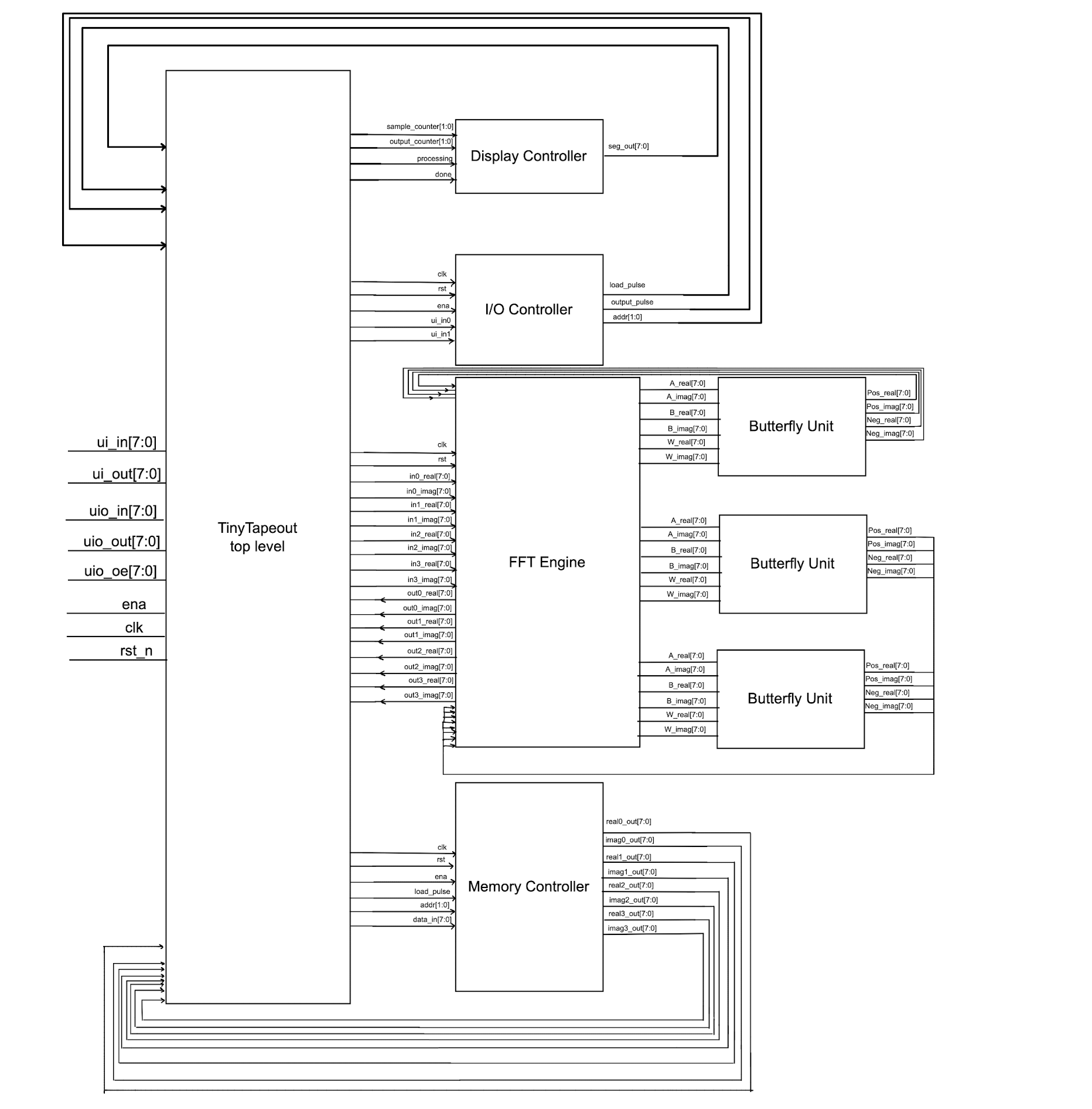
The architecture consists of several key components:
- Memory Controller: Manages sequential loading of 4 complex input samples via bidirectional data bus
- FFT Engine Core: Implements 4-point FFT algorithm using butterfly computation units
- I/O Controller: Manages input switches and output sequencing control
- Display Controller: Drives 7-segment display showing operation status
- Butterfly Computation Units: computes results
Processing Pipeline
The FFT computation follows a two-stage butterfly architecture:
Stage 1:
- Butterfly operation on input pairs (0,2) and (1,3)
- Uses twiddle factor W₀ = 1 (no multiplication needed)
Stage 2:
- Final butterfly operations with twiddle factor multiplication
- Uses W₁ = -j for appropriate frequency bin calculations
- Outputs 4 complex frequency domain results
Timing and Data Flow
- Processing Latency: Exactly 20 clock cycles from last input to first valid output
- Clock Frequency: 50 MHz operation
- Data Format: 8-bit complex samples (full 8-bit real and imaginary components)
- Sample Storage: Internal memory holds samples until FFT computation is triggered
Control Interface
The system uses a simple 2-button interface:
Switch 0 (Load Control):
- First toggle: Load sample 1
- Second toggle: Load sample 2
- Third toggle: Load sample 3
- Fourth toggle: Load sample 4
Switch 1 (Output Control):
- First toggle: Output frequency bin 1
- Second toggle: Output frequency bin 2
- Third toggle: Output frequency bin 3
- Fourth toggle: Output frequency bin 4
7-Segment Display Status
The display provides real-time operation feedback:
- 1-4: Currently inputting sample n
- C: Computing FFT (processing phase)
- 5-8: Currently outputting frequency bin n-4
FFT Engine INITIAL Design Document, NOT UP TO DATE USE DOCS IN REPO INSTEAD
How to Validate/test (Post Silicon)
Hardware Setup
Required Components:
- 7-segment display connected to
uo_out[7:0] - Input switches connected to
ui_in[1:0] - Bidirectional data interface on
uio[7:0]
Test Procedure
1. Input Phase
- Load Sample 1: Toggle Switch 0, apply first 8-bit complex sample to
uio[7:0] - Load Sample 2: Toggle Switch 0 again, apply second sample
- Load Sample 3: Toggle Switch 0 again, apply third sample
- Load Sample 4: Toggle Switch 0 again, apply fourth sample
Display shows "1", "2", "3", "4" during respective loading phases
2. Processing Phase
- FFT computation begins automatically after last sample loaded
- No user interaction required
3. Output Phase
- Read Bin 1: Toggle Switch 1, read first frequency bin from
uio[7:0] - Read Bin 2: Toggle Switch 1 again, read second frequency bin
- Read Bin 3: Toggle Switch 1 again, read third frequency bin
- Read Bin 4: Toggle Switch 1 again, read fourth frequency bin
Display shows "5", "6", "7", "8" during respective output phases
Data Format
Input Samples: Each 8-bit word represents one complex sample
- Real and imaginary components are full 8-bit signed values
- Input range: -128 to +127 for both real and imaginary parts
Output Results: Each 8-bit word represents one frequency bin
- Contains processed FFT result for that frequency
External hardware
- 7-segment display: Single digit display for status indication
- Input switches: 2 momentary or toggle switches for control
- Data interface: 8-bit bidirectional connection for samples/results
- Reset button: Connected to
rst_nfor system initialization
Pin Connections:
ui_in[0]: Load/Input control switchui_in[1]: Output/Read control switchuo_out[7:0]: 7-segment displayuio[7:0]: Bidirectional data bus (input samples / output results)rst_n: Active-low resetclk: 50 MHz system clock
Acknowledgements
This project was completed collaboratively, with both team members contributing to various components at different stages. A project proposal was designed jointly, and the initial division of responsibilities was as follows:
Hadi Zaidi: I/O Control, FFT Engine, Top Level design, Static Timing Analysis
Mariam El Sahhar: Memory, Butterfly Unit, Design Verification, Testbenches, Waveform Analysis
Throughout the project, both members provided support and input across all areas as needed. An earlier iteration can be found here.
IO
| # | Input | Output | Bidirectional |
|---|---|---|---|
| 0 | LOAD_BTN | SEG_0 | DATA_0 (sample input / FFT output) (bits 7:4 = real, bits 3:0 = imag for output) |
| 1 | OUTPUT_BTN | SEG_1 | DATA_1 |
| 2 | Unused | SEG_2 | DATA_2 |
| 3 | Unused | SEG_3 | DATA_3 |
| 4 | Unused | SEG_4 | DATA_4 |
| 5 | Unused | SEG_5 | DATA_5 |
| 6 | Unused | SEG_6 | DATA_6 |
| 7 | Unused | SEG_7 | DATA_7 |