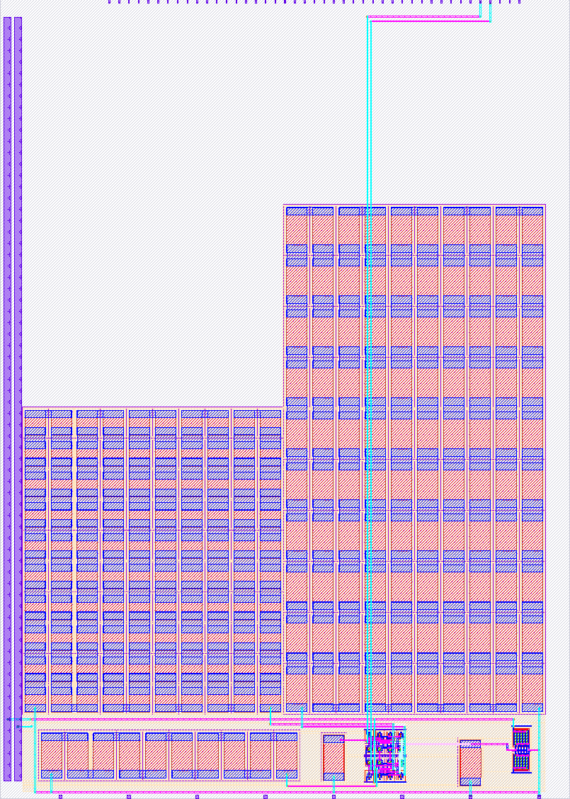
527 mixedsignal
527 : mixedsignal
- Author: Alexander Co Abad; Isabelle Rose Sta Rita
- Description: Inverter Biased for Linear Mode Operation
- GitHub repository
- Open in 3D viewer
- Clock: 0 Hz
- Feedback: ✅ 1
How it works
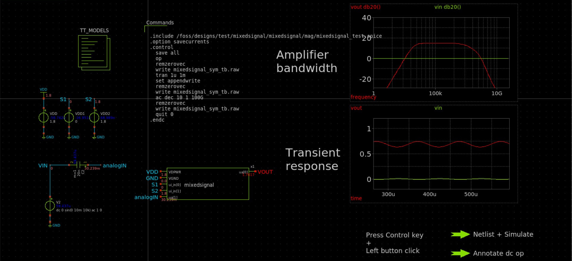
An inverter is biased for linear mode operation.
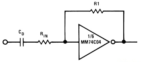
A multiplexer (MUX) is connected in parallel with the feedback resistor (R2 = 300 kΩ).
- By default, no additional resistor is connected in parallel.
- When the MUX selects a resistor, it is placed in parallel with R2, reducing the effective resistance and changing the gain.
The possible R2 effective values are:
- Default: 300 kΩ
- With 3 kΩ in parallel = ~2.97 kΩ
- With 30 kΩ in parallel = ~27.3 kΩ
- With 100 kΩ in parallel = ~75 kΩ
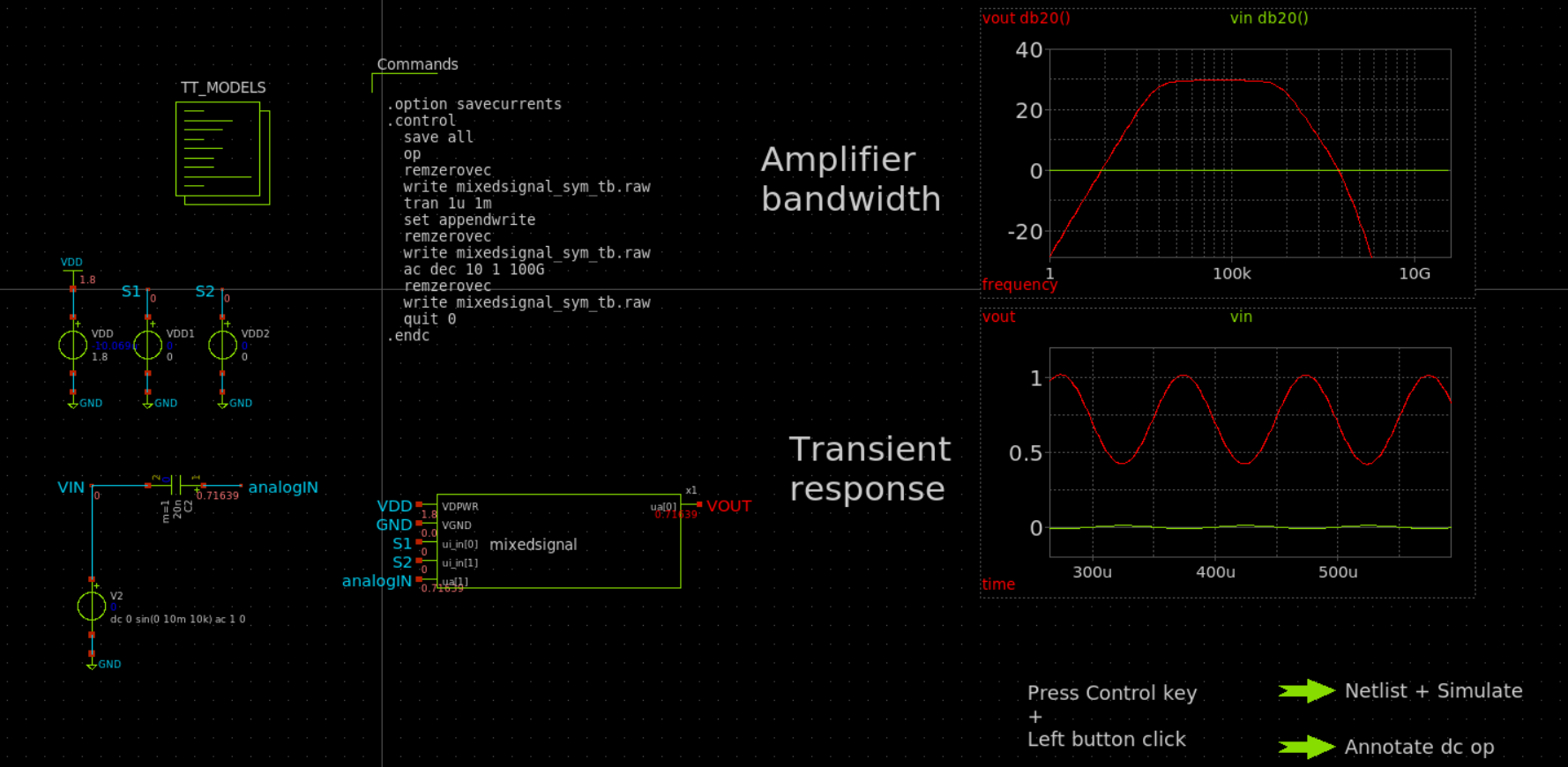
How to test
- Connect a 20 nF capacitor at the input.
- Apply the test input signal:
- DC offset = 0 V
- Amplitude = 10 mV
- Frequency = 10 kHz
- Observe the output waveform using an oscilloscope.
- Change the MUX selection (3 kΩ, 30 kΩ, or 100 kΩ) using the digital input pins (ui_in[0] and ui_in[1]) to vary the gain by changing the parallel resistance with R2.
- You may use the mixedsignal_sym_tb.sch testbench as a guide for the setup.
External hardware
- Oscilloscope
- 20 nF capacitor
Results
S1 = 0 & S2 = 0
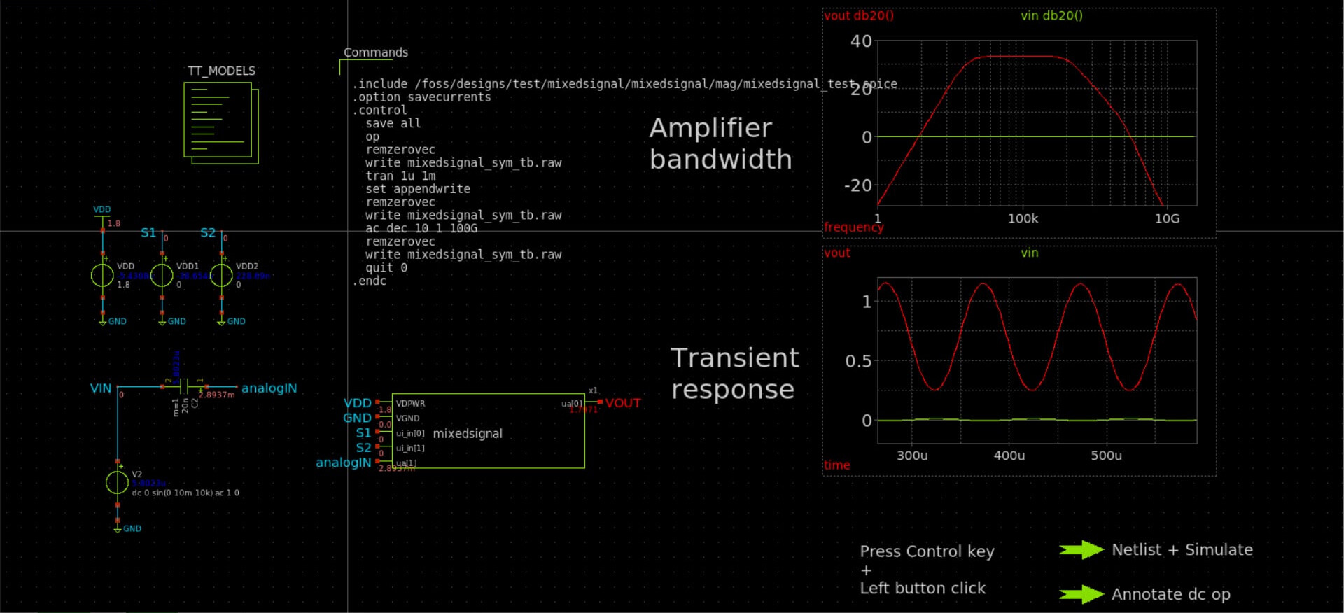
S1 = 0 & S2 = 1
S1 = 1 & S2 = 0

S1 = 1 & S2 = 1

IO
| # | Input | Output | Bidirectional |
|---|---|---|---|
| 0 | MUX selector 1 | ||
| 1 | MUX selector 2 | ||
| 2 | |||
| 3 | |||
| 4 | |||
| 5 | |||
| 6 | |||
| 7 |
Analog pins
ua | PCB Pin | Internal index | Description |
|---|---|---|---|
| 0 | B4 | 10 | analog output |
| 1 | B5 | 11 | analog input |
User feedback
- smunaut: Input is AC coupled, 100 kHz, 20 mV pp. Output : Mux 0: 637 mV, Mux 1: 222 mV, Mux 2: 151 mV, Mux 3: 340 mV,