973 freqSweep
973 : freqSweep
- Author: Jesus Minguillon
- Description: Frequency sweeper
- GitHub repository
- Open in 3D viewer
- Clock: 5000000 Hz
How it works
The project (src/project.v) implements a clock frequency sweeper in Verilog. It uses the Tiny Tapeout clock as input to generate a clock signal at the output uo[0] whose frequency is divided by 2 every 15 clock cycles. It goes from 1/2 to 1/16 of the input clock frequency and starts again. Input ui[0] is used as internal enable (active high).
How to test
For simulation, use the test bench (test/tb.v), which includes a module (src/periodCount.v) for measuring the frequency (or period) ratio between input and output clocks. Use the Python script (test/test.py) if you want to perform unit tests using cocotb. For hardware testing, make sure the internal enable (input ui[0]) is high and check the output clock at output uo[0] using an oscilloscope.
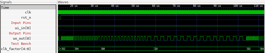
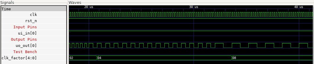
Gate level simulation (5 MHz input clock)
The frequency (or period) ratio between the input clock (clk) and the output clock (uo_out[0]) is given by clk_factor register of periodCount module:
Zoom in:
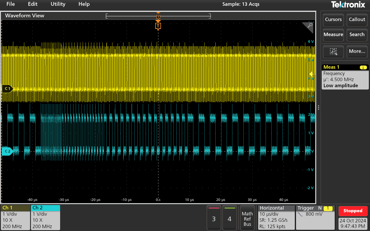
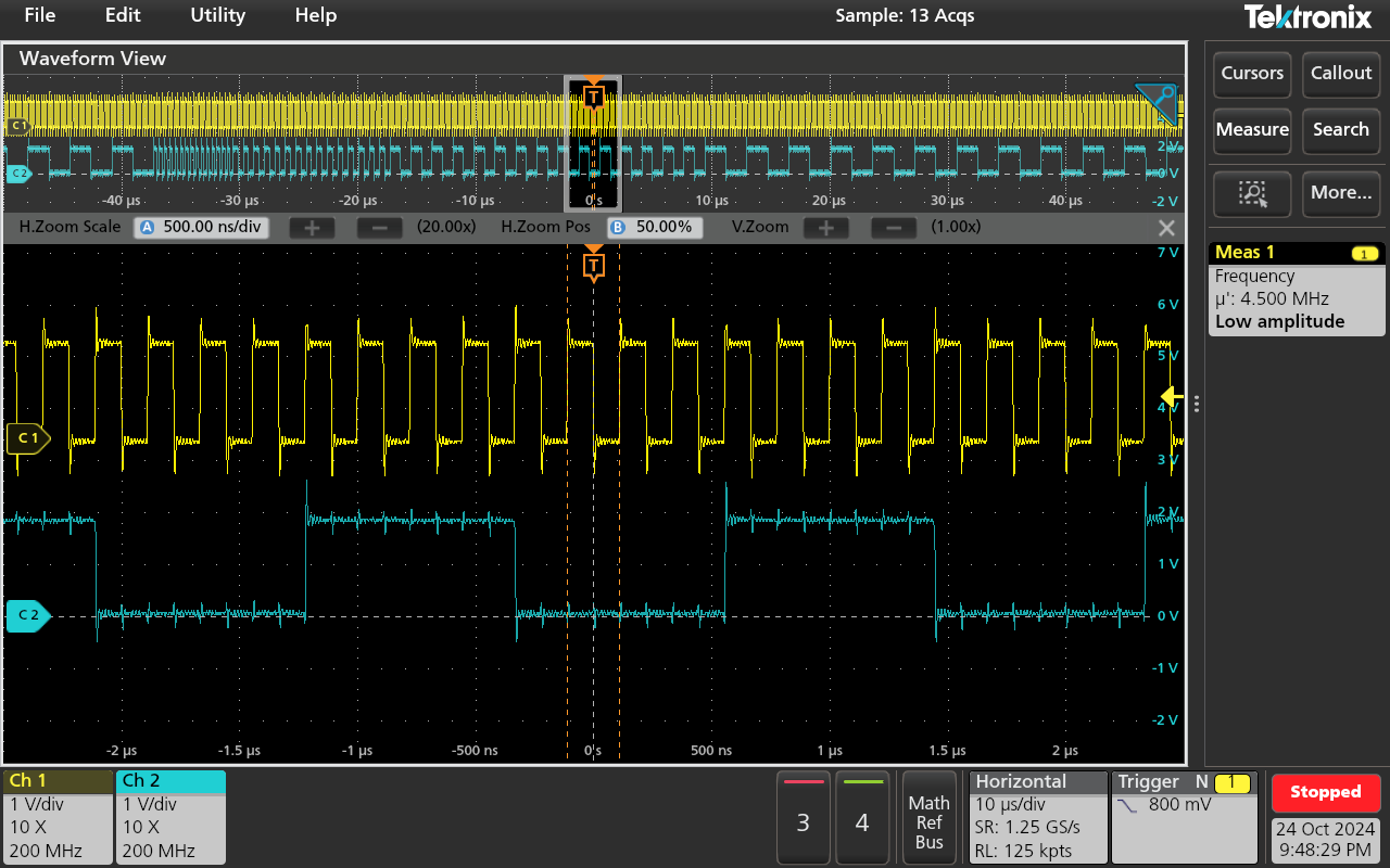
Test using Tang Nano 9K FPGA (4.5 MHz input clock)
Input clock signal (yellow) and ouput clock signal (blue) acquired with an oscilloscope (analog inputs and passive probes):
Zoom in:
IO
| # | Input | Output | Bidirectional |
|---|---|---|---|
| 0 | ui_in[0] | uo_out[0] | |
| 1 | |||
| 2 | |||
| 3 | |||
| 4 | |||
| 5 | |||
| 6 | |||
| 7 |