197 Array Multiplier
197 : Array Multiplier
- Author: Jaden Daily
- Description: 4x4 Structural Array Multiplier
- GitHub repository
- Open in 3D viewer
- Open in Tiny Tapeout Explorer
- Clock: 0 Hz
How it works
An array multiplier is a combinational circuit that multiplies two binary numbers together. The partial products are generated for each bit of the second operand and then adding them together using full adders. Each bit of the multiplier, in this case Q, produces partial products by using an AND-gate with every bit of M. Since this is a 4x4 multiplier, there will be 4 rows of 4-bit partial products. The partial products are then added together using full adders, with carry bits being moved to the next column as needed.
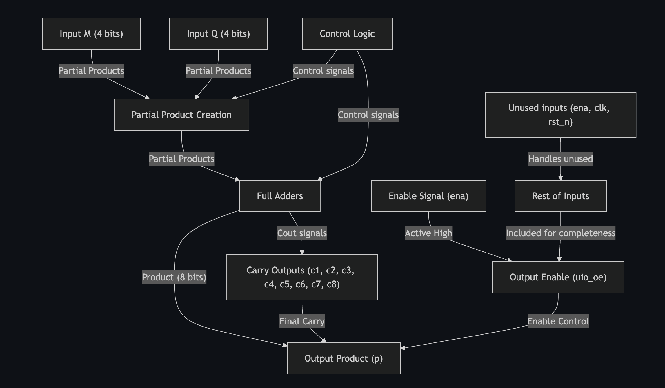
Block diagram
graph TD;
    M["Input M (4 bits)"] -->|"Partial Products"| PP["Partial Product Creation"]
    Q["Input Q (4 bits)"] -->|"Partial Products"| PP
    PP -->|"Partial Products"| FA["Full Adders"]
    FA -->|"Product (8 bits)"| P["Output Product (p)"]
    CL["Control Logic"] -->|"Control signals"| PP
    CL -->|"Control signals"| FA
    FA -->|"Cout signals"| C["Carry Outputs (c1, c2, c3, c4, c5, c6, c7, c8)"]
    C -->|"Final Carry"| P
    E["Enable Signal (ena)"] -->|"Active High"| OE["Output Enable (uio_oe)"]
    OE -->|"Enable Control"| P
    U["Unused inputs (ena, clk, rst_n)"] -->|"Handles unused"| W["Rest of Inputs"]
    W -->|"Included for completeness"| OE
Block diagram PDF
How to test
There are numerous ways of testing the hardware. One method is to use a simulation window with a provided testbench to verify that the output matches the inputs for each of the test cases. In this scenario, we have five separate test cases to ensure the hardware functions as needed. A separate check for minimum and maximum values to guarantee correct carry propagation is also required to ensure proper functionality.
IO
| # | Input | Output | Bidirectional |
|---|---|---|---|
| 0 | m[0] | p[0] | |
| 1 | m[1] | p[1] | |
| 2 | m[2] | p[2] | |
| 3 | m[3] | p[3] | |
| 4 | q[0] | p[4] | |
| 5 | q[1] | p[5] | |
| 6 | q[2] | p[6] | |
| 7 | q[3] | p[7] |