518 Twin Tee Sine Wave Generator
518 : Twin Tee Sine Wave Generator

- Author: Matt Venn
- Description: Opamp plus notch filter = sine wave out
- GitHub repository
- Open in 3D viewer
- Clock: 0 Hz
- Feedback: ✅ 1
How it works
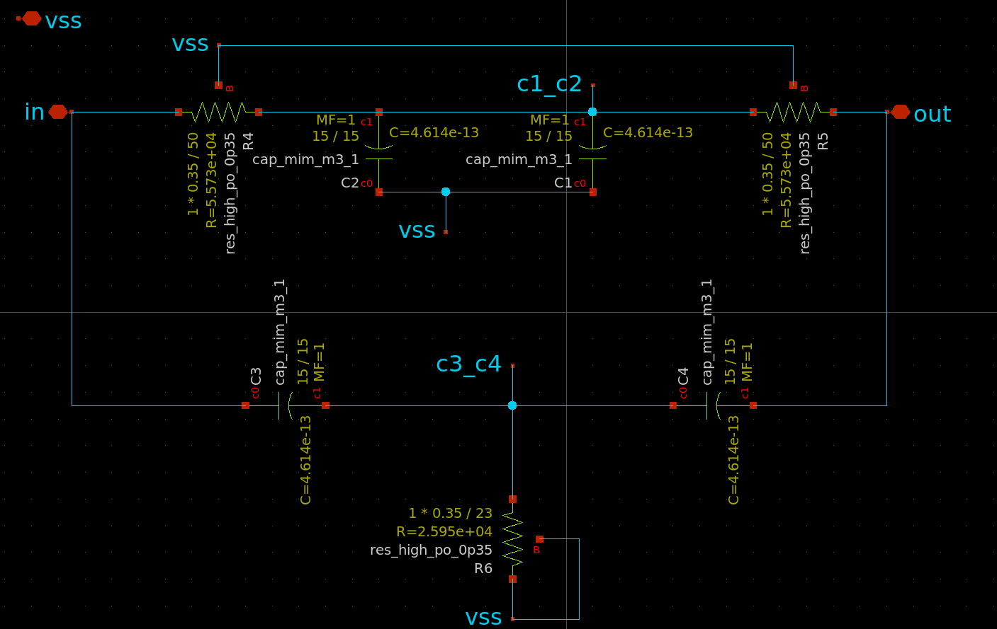
The circuit uses a "Twin Tee" filter along with an opamp to generate a sine wave.

https://www.electronics-tutorials.ws/oscillator/twin-t-oscillator.html
f = 1 / 2 * pi * RC
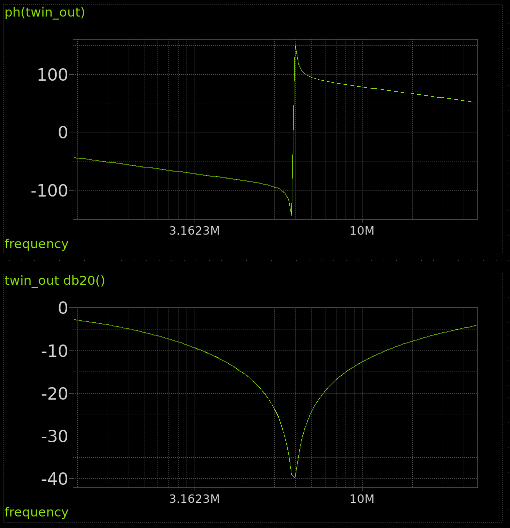
Notch filter AC analysis

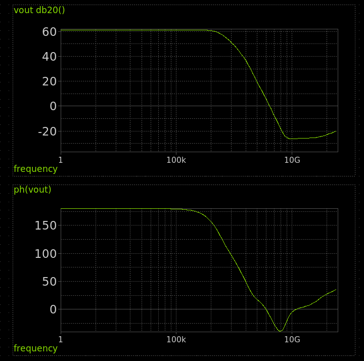
Opamp AC analysis

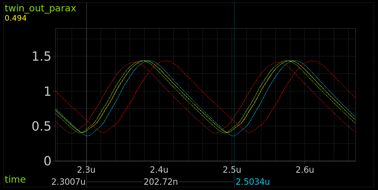
Transient analysis
This simulation was done with a "montecarlo mismatch corner" which aims to test how well the circuit will work as the resistance and transistors change across process corners. Each run is shown in a different colour. If R6 resistor in the Twin Tee filter is too high, the oscillations quickly die out, so it's deliberately undersized at the expense of distortion in the sine wave.
This simulation includes extracted parastitics and a model of the pin.

Acknowledgements
- The opamp design comes from Sai
- The opamp layout comes from Pat Deegan
- Inspired by this video by Alan Wolke.
How to test
After the project is enabled, you should see a sine wave at around 4.93MHz on analog output pin 0.
There is also a 20 bit digital counter connected to the oscillator output. The top 8 bits are connected to the LEDs. So you should also see the most significant bit (the dot) flashing about 5 times per second.
External hardware
Oscilloscope.
Silicon results
The measurement was made with a Keysight HD3 scope. The design is very sensitive to loading, so a scope probe was connected direct to the pad (after removing the pulldown).
![]()
The frequency was measured at 4.67MHz, which is about 5% slower than anticipated.
IO
| # | Input | Output | Bidirectional |
|---|---|---|---|
| 0 | counter bit 12 | ||
| 1 | counter bit 13 | ||
| 2 | counter bit 14 | ||
| 3 | counter bit 15 | ||
| 4 | counter bit 16 | ||
| 5 | counter bit 17 | ||
| 6 | counter bit 18 | ||
| 7 | counter bit 19 |
Analog pins
ua | PCB Pin | Internal index | Description |
|---|---|---|---|
| 0 | B5 | 11 | sine out |
User feedback
- mattvenn👑: Oscillates at ~4.6MHz. The 7 segment counts correctly. Not a very good sine wave, but not too bad. The design is quite sensitive to loading so start it up with no scope connected.